Toyota Venza: Rear Wheel Alignment
Adjustment
ADJUSTMENT
PROCEDURE
1. INSPECT TIRES
(a) Inspect the tires (See page .gif) ).
).
2. MEASURE VEHICLE HEIGHT
3. INSPECT CAMBER
Camber (Unloaded Vehicle):
|
Model |
Engine |
Camber Inclination |
Right-left Difference |
|---|---|---|---|
|
2WD |
1AR-FE |
-1°13' +/- 45' (-1.22° +/- 0.75°) |
45' (0.75°) or less |
|
2GR-FE |
-1°14' +/- 45' (-1.23° +/- 0.75°) |
||
|
AWD |
1AR-FE |
-0°47' +/- 45' (-0.78° +/- 0.75°) |
|
|
2GR-FE |
-0°48' +/- 45' (-0.80° +/- 0.75°) |
HINT:
Camber is not adjustable. If the measurement is not within the specified range, inspect the suspension parts for damage and/or wear, and replace them if necessary.
4. INSPECT TOE-IN
Toe-in (Unloaded Vehicle):
|
Model |
Specified Condition |
Right-left Difference |
|---|---|---|
|
2WD |
C + D: 0°17' +/- 0°10' (0.28° +/- 0.16°) |
30' (0.50°) or less |
|
B - A: 3.8 +/- 2.0 mm (0.150 +/- 0.0787 in.) |
- |
|
|
AWD |
C + D: 0°16' +/- 0°10' (0.27° +/- 0.16°) |
30' (0.50°) or less |
|
B - A: 3.6 +/- 2.0 mm (0.142 +/- 0.0787 in.) |
- |
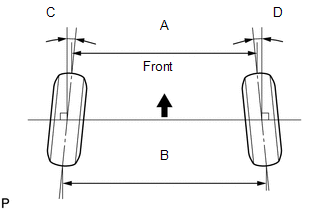
If the toe-in is not within the specified range, adjust it at the rear No. 2 suspension arms.
HINT:
Measure "B - A" only when "C + D" cannot be measured.
5. ADJUST TOE-IN (for 2WD)
|
(a) Measure the lengths of the right and left rear No. 2 suspension arms. Difference in the length of rear No. 2 suspension arms: 1.5 mm (0.0590 in.) or less If the left-right difference is larger than 1.5 mm (0.0590 in.), adjust it by following the procedures below. |
|
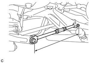
|
(b) Loosen the 2 lock nuts. |
|
(c) If the length difference between the left and right rear No. 2 suspension arm assemblies is not within the specified range, adjust it by following the procedures below.
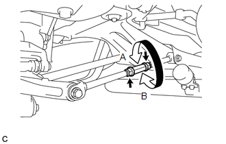
(1) If the toe-in measurement is greater than the specified range, extend the shorter rear No. 2 suspension arm assembly by rotating the adjusting tube in the direction of arrow B in the illustration.
(2) If the toe-in measurement is less than the specified range, shorten the longer rear No. 2 suspension arm assembly by rotating the adjusting tube in the direction of arrow A in the illustration.
(3) Measure the toe-in.
(d) Turn the right and left adjusting tubes by an equal amount to adjust toe-in.
HINT:
- Try to adjust the toe-in to the center of the specified range.
- One turn of each adjusting tube will adjust the toe-in by approximately 11.1 mm (0.437 in.).
(e) Tighten the lock nuts while securing the adjusting tube in the order indicated below:
Torque:
56 N·m {571 kgf·cm, 41 ft·lbf}
- Tighten the outside lock nut.
- Tighten the inside lock nut.
- Retighten the outside lock nut.
6. ADJUST TOE-IN (for AWD)
(a) Measure the distance between each wheel disc and the center of the toe-adjusting cam.
Difference in the distance between each wheel disc and the center of the toe-adjusting cam:
1.0 mm (0.0393 in.) or less
If the left-right difference is larger than 1.0 mm (0.0393 in.), adjust it by following the procedures below.
|
(b) Loosen the toe-adjust cam set nuts. |
|
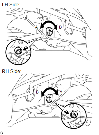
(c) If the distance between each wheel disc and the center of the toe-adjusting cam is not within the specified range, adjust it by following the procedures below.
(1) If the toe-in measurement is greater than the specified range, extend the shorter rear No. 2 suspension arm assembly by rotating the adjust cams in the direction of arrow B in the illustration.
(2) If the toe-in measurement is less than the specified range, shorten the longer rear No. 2 suspension arm assembly by rotating the adjust cams in the direction of arrow A in the illustration.
(3) Measure the toe-in.
(d) Turn the adjust cams by an equal amount to adjust toe-in.
HINT:
- Try to adjust the toe-in to the center of the specified range.
- One graduation of each adjusting cam will adjust the toe-in by approximately 3.3 mm (0.130 in.).
(e) Tighten the toe-adjust cam set nuts.
Torque:
100 N·m {1020 kgf·cm, 74 ft·lbf}
NOTICE:
The final torque must be applied under standard vehicle height conditions.
 Adjustment
ADJUSTMENT
PROCEDURE
1. INSPECT TIRES
(a) Inspect the tires (See page ).
2. MEASURE VEHICLE HEIGHT
NOTICE:
Before inspecting the wheel alignment, adjust the vehicle height to
the sp ...
 Front Suspension
...
Other materials about Toyota Venza:
Inspection
INSPECTION
PROCEDURE
1. INSPECT NO. 1 ULTRASONIC SENSOR
(a) Measure the resistance according to the value(s) in the table below.
Standard Resistance:
Tester Connection
Condition
Specified ...
Removal
REMOVAL
CAUTION / NOTICE / HINT
NOTICE:
Do not replace the spiral cable with the battery connected and the ignition
switch ON.
Do not rotate the spiral cable without the steering wheel with the battery
connected and the ignition switch O ...
Satellite Radio Antenna
Components
COMPONENTS
ILLUSTRATION
ILLUSTRATION
Removal
REMOVAL
PROCEDURE
1. REMOVE ROOF HEADLINING ASSEMBLY
(See page )
2. REMOVE ROOF ANTENNA POLE SUB-ASSEMBLY
3. REMOVE SATELLITE RADIO ANTENNA ASSEMBLY
(a) Disconnect the co ...

0.1197