Toyota Venza: Rear Center Seat Inner Belt Assembly
Components
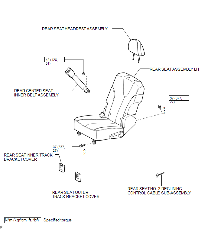
COMPONENTS
ILLUSTRATION
Removal
REMOVAL
PROCEDURE
1. REMOVE REAR SEAT HEADREST ASSEMBLY
.gif)
2. REMOVE REAR SEAT INNER TRACK BRACKET COVER
3. REMOVE REAR SEAT OUTER TRACK BRACKET COVER
4. DISCONNECT REAR SEAT NO. 2 RECLINING CONTROL CABLE SUB-ASSEMBLY
5. REMOVE REAR SEAT ASSEMBLY LH
6. REMOVE REAR CENTER SEAT INNER BELT ASSEMBLY
|
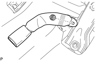
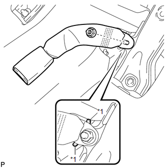
(a) Remove the nut and the rear center seat inner belt assembly. |
|
Installation
INSTALLATION
PROCEDURE
1. INSTALL REAR CENTER SEAT INNER BELT ASSEMBLY
|
(a) Install the rear center seat inner belt assembly with the nut. Text in Illustration
Torque: 42 N·m {428 kgf·cm, 31 ft·lbf} NOTICE: Do not allow the anchor part of the rear seat outer belt assembly to overlap the protruding part of the floor panel. |
|
2. INSTALL REAR SEAT ASSEMBLY LH
.gif)
3. CONNECT REAR SEAT NO. 2 RECLINING CONTROL CABLE SUB-ASSEMBLY
4. INSTALL REAR SEAT INNER TRACK BRACKET COVER
5. INSTALL REAR SEAT OUTER TRACK BRACKET COVER
6. INSTALL REAR SEAT HEADREST ASSEMBLY
 Disposal
DISPOSAL
CAUTION / NOTICE / HINT
CAUTION:
Before performing pre-disposal deployment of any SRS component, review and closely
follow all applicable environmental and hazardous material regulations ...

Other materials about Toyota Venza:
Operation Check
OPERATION CHECK
1. CHECK PANEL & STEERING SWITCH
HINT:
The radio and display receiver assembly panel switches and steering
switches are checked in the following procedure.
Illustrations may differ from the actual vehicle screen depending ...
Installation
INSTALLATION
PROCEDURE
1. INSTALL DRIVE MONITOR SWITCH
(a) Engage the 4 claws to install the drive monitor switch.
2. INSTALL RADIO AND DISPLAY RECEIVER ASSEMBLY WITH BRACKET (for Radio and Display
Type)
3. INSTALL NAVIGATION RECEIVER ASSEMBLY WITH B ...
Personal Light
Components
COMPONENTS
ILLUSTRATION
Removal
REMOVAL
PROCEDURE
1. REMOVE MAP LIGHT ASSEMBLY
(a) Using a moulding remover, disengage the 2 claws and 2 clips.
Text in Illustration
*1
Fastener
...

0.1448