Toyota Venza: Purge Valve
Components
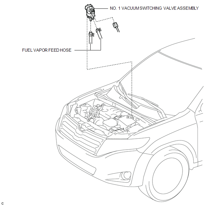
COMPONENTS
ILLUSTRATION
Inspection
INSPECTION
PROCEDURE
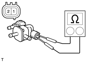
1. INSPECT NO. 1 VACUUM SWITCHING VALVE ASSEMBLY
|
(a) Measure the resistance according to the value(s) in the table below. Standard Resistance:
If the result is not as specified, replace the No. 1 vacuum switching valve assembly. |
|
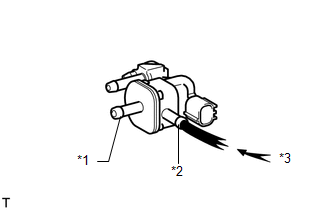
(b) Check the operation of the No. 1 vacuum switching valve assembly.
|
(1) Check that air does not flow from port F when air is applied to port E. Text in Illustration
|
|
|
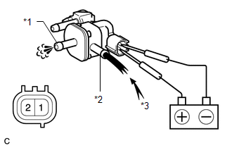
(2) Apply battery voltage to the connector, and check the VSV operation. Text in Illustration
OK:
If the result is not as specified, replace the No. 1 vacuum switching valve assembly. |
|
Removal
REMOVAL
PROCEDURE
1. REMOVE NO. 1 VACUUM SWITCHING VALVE ASSEMBLY
|
(a) Disconnect the connector and 2 fuel vapor feed hoses. |
|
|
(b) Remove the No. 1 vacuum switching valve assembly. |
|
Installation
INSTALLATION
PROCEDURE
1. INSTALL NO. 1 VACUUM SWITCHING VALVE ASSEMBLY
|
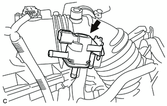
(a) Install the No. 1 vacuum switching valve assembly. |
|
.png)
|
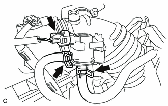
(b) Connect the connector and 2 fuel vapor feed hoses. |
|
.png)
 Pcv Valve
Components
COMPONENTS
ILLUSTRATION
Removal
REMOVAL
PROCEDURE
1. REMOVE INTAKE MANIFOLD
(a) Remove the intake manifold (See page ).
2. REMOVE VENTILATION VALVE SUB-ASSEMBLY
( ...

Other materials about Toyota Venza:
Reassembly
REASSEMBLY
PROCEDURE
1. INSTALL FRONT SEAT WIRE
(a) Engage the 2 clamps to install the front seat wire.
(b) Connect the 4 connectors.
2. INSTALL OCCUPANT CLASSIFICATION ECU
3. INSTALL FRONT LOW ...
Reassembly
REASSEMBLY
PROCEDURE
1. BEARING POSITION
(a) Check each bearing position and installation direction.
Mark
Front Race Diameter
Inside / Outside mm (in.)
Thrust Bearing Diameter
Inside / Outside mm (in.)
...
Removal
REMOVAL
PROCEDURE
1. REMOVE REAR WHEELS
2. REMOVE REAR STABILIZER LINK ASSEMBLY LH
(a) Remove the nut and separate the rear stabilizer link assembly LH
from the rear stabilizer bar.
Text in Illustration
*1
...

0.1571