Toyota Venza: Lost Communication with Power Source Control (B278C)
DESCRIPTION
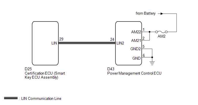
This DTC is stored when LIN communication between the certification ECU (smart key ECU assembly) and power management control ECU stops for more than 10 seconds.
|
DTC Code |
DTC Detection Condition |
Trouble Area |
|---|---|---|
|
B278C |
No communication between the certification ECU (smart key ECU assembly) and power management control ECU for more than 10 seconds. |
|
WIRING DIAGRAM
CAUTION / NOTICE / HINT
NOTICE:
- If the certification ECU (smart key ECU assembly) is replaced, register the key.
- When using the Techstream to troubleshoot with the ignition switch off:
Connect the Techstream to the DLC3, and turn the courtesy switch on and off at 1.5-second intervals until communication between the Techstream and vehicle begins.
PROCEDURE
|
1. |
CHECK HARNESS AND CONNECTOR (POWER MANAGEMENT CONTROL ECU - BATTERY AND BODY GROUND) |
|
(a) Disconnect the D43 ECU connector. |
|
(b) Measure the resistance and voltage according to the value(s) in the table below.
Standard Resistance:
|
Tester Connection |
Condition |
Specified Condition |
|---|---|---|
|
D43-5 (GND2) - Body ground |
Always |
Below 1 Ω |
|
D43-6 (GND) - Body ground |
Always |
Below 1 Ω |
Standard Voltage:
|
Tester Connection |
Condition |
Specified Condition |
|---|---|---|
|
D43-1 (AM22) - Body ground |
Always |
11 to 14 V |
|
D43-2 (AM21) - Body ground |
Always |
11 to 14 V |
|
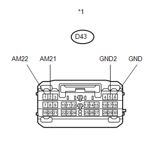
*1 |
Power Management Control ECU |
| NG | .gif) |
REPAIR OR REPLACE HARNESS OR CONNECTOR |
|
.gif)
|
2. |
CHECK HARNESS AND CONNECTOR (CERTIFICATION ECU - POWER MANAGEMENT CONTROL ECU) |
|
(a) Disconnect the D25 ECU connector. |
|
(b) Measure the resistance according to the value(s) in the table below.
Standard Resistance:
|
Tester Connection |
Condition |
Specified Condition |
|---|---|---|
|
D25-29 (LIN) - D43-24 (LIN2) |
Always |
Below 1 Ω |
|
D25-29 (LIN) - Body ground |
Always |
10 kΩ or higher |
|
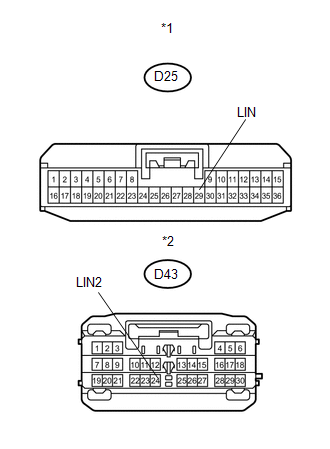
*1 |
Front view of wire harness connector (to Certification ECU (Smart Key ECU Assembly)) |
|
*2 |
Front view of wire harness connector (to Power Management Control ECU) |
| NG | |
REPAIR OR REPLACE HARNESS OR CONNECTOR |
|
|
3. |
REPLACE POWER MANAGEMENT CONTROL ECU |
(a) Replace the power management control ECU (See page
.gif) ).
).
|
|
4. |
CHECK DTC OUTPUT |
(a) Clear the DTC (See page ).
(b) Recheck for DTCs.
OK:
DTC B278C is not output.
| OK | |
END (POWER MANAGEMENT CONTROL ECU WAS DEFECTIVE) |
| NG | |
REPLACE CERTIFICATION ECU (SMART KEY ECU ASSEMBLY) |
 Data List / Active Test
DATA LIST / ACTIVE TEST
1. DATA LIST
HINT:
Using the Techstream to read the Data List allows the values or states of switches,
sensors, actuators and other items to be read without removing any p ...
 Diagnostic Trouble Code Chart
DIAGNOSTIC TROUBLE CODE CHART
Main Body ECU (Driver Side junction Block Assembly)
DTC Code
Detection Item
Trouble Area
See page
B1206
...
Other materials about Toyota Venza:
Terminals Of Ecu
TERMINALS OF ECU
1. CHECK MAIN BODY ECU (DRIVER SIDE JUNCTION BLOCK ASSEMBLY)
(a) Disconnect the 2A, 2C and 2F main body ECU (driver side junction block assembly)
connectors.
(b) Measure the voltage and resistance according to the value(s) in the table ...
Freeze Frame Data
FREEZE FRAME DATA
1. FREEZE FRAME DATA
(a) Whenever a DTC is detected, the AFS ECU (headlight swivel ECU assembly) stores
the current vehicle (sensor) state as Freeze Frame Data.
2. CHECK FREEZE FRAME DATA
(a) Connect the Techstream to the DLC3.
(b) Tur ...
CD cannot be Ejected
PROCEDURE
1.
CHECK OPERATION
(a) Press the disc eject switch of the radio and display receiver assembly for
5 seconds or more and check that the CD is ejected.
OK:
CD is ejected.
NG
REPLACE RADIO AND D ...

0.1207