Toyota Venza: Pcv Valve
Components
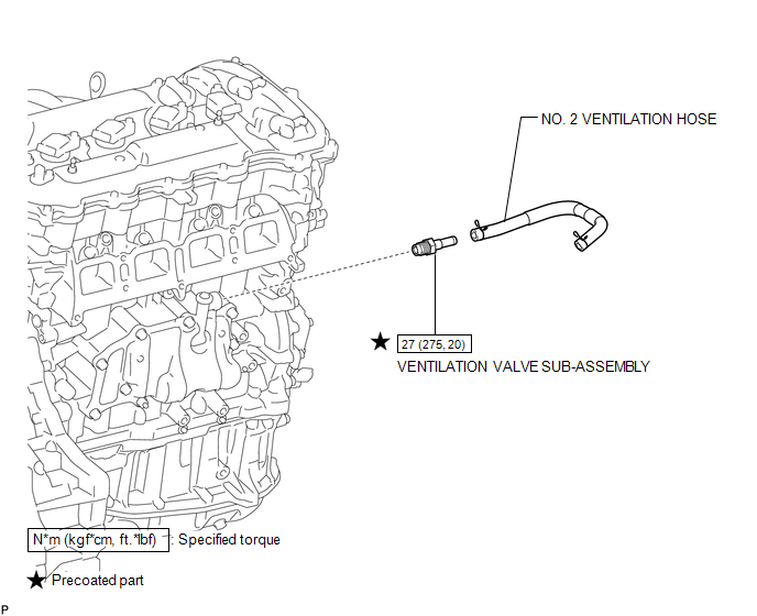
COMPONENTS
ILLUSTRATION
Removal
REMOVAL
PROCEDURE
1. REMOVE INTAKE MANIFOLD
(a) Remove the intake manifold (See page .gif) ).
).
2. REMOVE VENTILATION VALVE SUB-ASSEMBLY
|
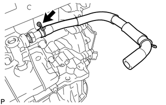
(a) Disconnect the No. 2 ventilation hose from the ventilation valve. |
|
|
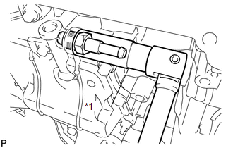
(b) Using a 19 mm deep socket wrench, remove the ventilation valve. Text in Illustration
|
|
Inspection
INSPECTION
PROCEDURE
1. INSPECT VENTILATION VALVE SUB-ASSEMBLY
|
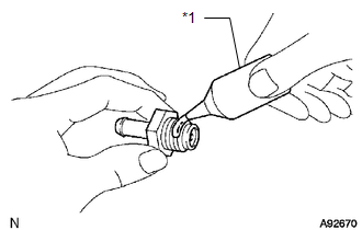
(a) Install a clean hose to the ventilation valve. |
|
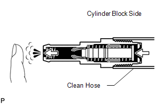
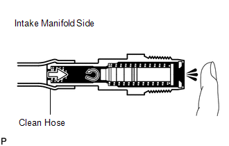
(b) Check the ventilation valve operation.
(1) Blow air into the cylinder block side and check that air passes through easily.
If the result is not as specified, replace the ventilation valve sub-assembly.
CAUTION:
Do not suck air through the valve.
Petroleum substances inside the valve are hazardous to your health.
|
(2) Blow air into the intake manifold side and check that air passes through with difficulty. If the result is not as specified, replace the ventilation valve sub-assembly. |
|
(c) Remove the clean hose from the ventilation valve.
Installation
INSTALLATION
PROCEDURE
1. INSTALL VENTILATION VALVE SUB-ASSEMBLY
|
(a) Apply adhesive to 2 or 3 threads of the ventilation valve. Text in Illustration
Adhesive: Toyota genuine adhesive 1324, three bond 1324 or equivalent |
|
|
(b) Using a 19 mm deep socket wrench, install the ventilation valve. Text in Illustration
Torque: 27 N·m {275 kgf·cm, 20 ft·lbf} |
|
.png)
|
(c) Connect the No. 2 ventilation hose to the ventilation valve. |
|
.png)
2. INSTALL INTAKE MANIFOLD
(a) Install the intake manifold (See page .gif)
).
3. INSPECT FOR OIL LEAK
 Fuel Tank Cap
Inspection
INSPECTION
PROCEDURE
1. INSPECT FUEL TANK CAP ASSEMBLY
(a) Visually check that the fuel tank cap assembly and gasket are not
deformed or damaged.
Text in Illustratio ...
 Purge Valve
Components
COMPONENTS
ILLUSTRATION
Inspection
INSPECTION
PROCEDURE
1. INSPECT NO. 1 VACUUM SWITCHING VALVE ASSEMBLY
(a) Measure the resistance according to the value(s) in the ...
Other materials about Toyota Venza:
Problem Symptoms Table
PROBLEM SYMPTOMS TABLE
HINT:
Use the table below to help determine the cause of problem symptoms.
If multiple suspected areas are listed, the potential causes of the symptoms
are listed in order of probability in the "Suspected Area" ...
How To Proceed With Troubleshooting
CAUTION / NOTICE / HINT
HINT:
Use the following procedure to troubleshoot the power window control
system.
*: Use the Techstream.
PROCEDURE
1.
VEHICLE BROUGHT TO WORKSHOP
NEXT
...
Brake Line
Precaution
PRECAUTION
1. TROUBLESHOOTING PRECAUTION
NOTICE:
Since the brake lines are critical safety related parts, be sure to
disassemble and inspect the components if a brake fluid leak is found. If
any abnormality is found, replace th ...

0.1593