Toyota Venza: PS Warning Light Remains ON
DESCRIPTION
If the power steering ECU detects a malfunction, the P/S warning light comes on. At this time, the power steering ECU stores a DTC in its memory.
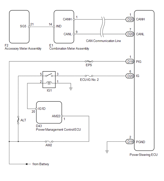
WIRING DIAGRAM
1. w/ Smart Key System
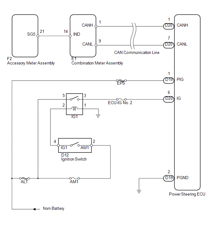
2. w/o Smart Key System
CAUTION / NOTICE / HINT
NOTICE:
If the power steering ECU has been replaced with a new one, perform the rotation
angle sensor initialization and torque sensor zero point calibration (See page
.gif) ).
).
PROCEDURE
|
1. |
CHECK HARNESS AND CONNECTOR |
(a) Turn the ignition switch to ON.
(b) Check the indication condition of the P/S warning light by wiggling the power steering ECU connector and wire harness up and down, and right and left.
OK:
P/S warning light indication condition does not change.
| NG | .gif) |
REPAIR OR REPLACE HARNESS OR CONNECTOR |
|
.gif)
|
2. |
CHECK FOR DTC (CAN COMMUNICATION SYSTEM) |
(a) Check for DTCs (See page ).
OK:
DTC is not output.
| NG | |
GO TO CAN COMMUNICATION SYSTEM |
|
|
3. |
READ VALUE USING TECHSTREAM (IG POWER SUPPLY) |
(a) Turn the ignition switch off.
(b) Connect the Techstream to the DLC3.
(c) Turn the ignition switch to ON.
(d) Turn the Techstream on.
(e) Enter the following menus: Chassis / EMPS / Data List.
(f) Select the items "IG Power Supply" in the Data List and read the value displayed on the Techstream.
EMPS|
Tester Display |
Measurement Item/Range |
Normal Condition |
Diagnostic Note |
|---|---|---|---|
|
IG Power Supply |
ECU power source voltage/ Min.: 0 V Max.: 20.1531 V |
11 to 14 V |
Ignition switch ON |
OK:
Normal condition value is displayed the Techstream.
Result|
Result |
Proceed to |
|---|---|
|
OK |
A |
|
NG (for 2GR-FE) |
B |
|
NG (for 1AR-FE) |
C |
| B | |
INSPECT CHARGING SYSTEM |
| C | |
INSPECT CHARGING SYSTEM |
|
|
4. |
CHECK HARNESS AND CONNECTOR (POWER STEERING ECU - BODY GROUND) |
|
(a) Disconnect the connectors from the power steering ECU. |
|
.png)
(b) Measure the voltage according to the value(s) in the table below.
Standard Voltage:
|
Tester Connection |
Switch Condition |
Specified Condition |
|---|---|---|
|
D20-6 (IG) - Body ground |
Ignition switch ON |
11 to 14 V |
(c) Measure the resistance according to the value(s) in the table below.
Standard Resistance:
|
Tester Connection |
Condition |
Specified Condition |
|---|---|---|
|
D19-2 (PGND) - Body ground |
Always |
Below 1 Ω |
|
*1 |
Front view of wire harness connector (to Power Steering ECU) |
| NG | |
REPAIR OR REPLACE HARNESS OR CONNECTOR |
|
|
5. |
REPLACE POWER STEERING ECU |
(a) Replace the power steering ECU (See page
).
(b) Check the P/S warning light condition.
OK:
P/S warning light remains on when the ignition switch is ON and goes off after engine start.
| OK | |
END |
| NG | |
GO TO METER / GAUGE SYSTEM |
 Torque Sensor Zero Point Adjustment Undone (C1515,C1525)
DESCRIPTION
These DTCs do not indicate a malfunction. The power steering ECU stores these
DTCs when it determines that the rotation angle sensor value initialization and
torque sensor zero point ...
 Steering Column
...
Other materials about Toyota Venza:
Diagnostic Trouble Code Chart
DIAGNOSTIC TROUBLE CODE CHART
Audio and Visual System
DTC Code
Detection Item
See page
B1532
LVDS Signal Malfunction (from Extension Module)
B1551
HD Radio ...
Installation
INSTALLATION
PROCEDURE
1. INSTALL FUEL LID LOCK CONTROL CABLE SUB-ASSEMBLY
(a) Engage the 8 clamps.
(b) Engage the 2 claws and connect the fuel lid lock control cable sub-assembly.
2. INSTALL FUE ...
Disassembly
DISASSEMBLY
PROCEDURE
1. REMOVE GENERATOR PULLEY CAP
(a) Using a screwdriver, puncture the center of the generator pulley
cap and pry it off.
NOTICE:
Do not reuse the generator pulley cap.
...

0.1565