Toyota Venza: Engine (ignition) switch (vehicles without smart key system)
- Starting the engine
 Check that the parking brake is
set.
 Check that the shift lever is set
in “P”.
 Sit in the driver’s seat and firmly
depress the brake pedal.
 Turn the engine switch to the “START”
position and start the engine.
- Engine (ignition) switch
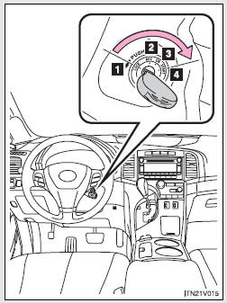
1. “LOCK”
The steering wheel is locked and the key can be removed.
(The key can be removed only when the shift lever is in “P”.) 2. “ACC” Some electrical components such as the audio system can be used.
3. “ON”
All electrical components can be used.
4. “START”
For starting the engine.
- Turning the key from “ACC” to “LOCK”
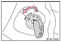
Shift the shift lever to “P”.
Push in the key and turn to the
“LOCK” position.
- When the steering lock cannot be released
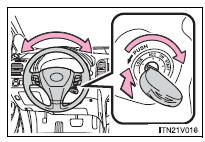
When starting the engine, the engine switch may seem stuck in the “LOCK” position. To free it, turn the key while turning the steering wheel slightly in either direction.
- If the engine does not start
The engine immobilizer system may not have been deactivated.
- Key reminder function
A buzzer sounds if the driver’s door is opened, while the engine switch is in “LOCK” or “ACC” position to remind you to remove the key.
CAUTION
- When starting the engine
Always start the engine while sitting in the driver’s seat. Do not depress the accelerator pedal while starting the engine under any circumstances.
Doing so may cause an accident resulting in death or serious injury.
- While driving
Do not turn the engine switch to the “LOCK” position.
If in an emergency, you must turn the engine off while the vehicle is moving, turn the key only to the “ACC” position.
NOTICE
- To prevent battery discharge
Do not leave the key in the “ACC” or “ON” position for long periods without the engine running.
- When starting the engine
• Do not crank for more than 30 seconds at a time. This may overheat the starter and wiring systems.
• Do not race the cold engine.
• If the engine becomes difficult to start or stalls frequently, have the engine checked immediately.
 Engine (ignition) switch (vehicles with smart key system)
Performing the following operations when carrying the electronic key on your
person starts the engine or changes “ENGINE START STOP” switch modes.
- Starting the engine
Check that the pa ...
 Automatic transmission
Select a shift position appropriate for the driving conditions.
- Shifting the shift lever
Vehicles with smart key system:
While the “ENGINE START STOP” switch is in IGNITION ON mode, d ...
Other materials about Toyota Venza:
Transmitter ID not Registered (C2171/71)
DESCRIPTION
Each tire pressure warning valve and transmitter ID is registered to the tire
pressure warning ECU.
When the ECU detects a transmitter ID code not registered in the ECU, a DTC is
output.
DTC No.
DTC Detection Condition
...
TRAC OFF Indicator Light Remains ON
DESCRIPTION
The skid control ECU is connected to the combination meter via CAN communication.
Pressing the VSC OFF switch turns off traction control and pressing and holding
this switch turns off traction and VSC controls. If TRAC control is turned off,
...
Air Inlet Damper Control Servo Motor Circuit (B1442/42)
DESCRIPTION
The air inlet control servo motor sends pulse signals to indicate the damper
position to the A/C amplifier. The A/C amplifier activates the motor (normal or
reverse) based on these signals to move the air inlet mode selection air inlet control ...

0.1296