Toyota Venza: Power Source Mode does not Change to ON (ACC)
DESCRIPTION
When the engine switch is pushed with the electrical key in the cabin, the power management control ECU receives signals to change the power source mode.
HINT:
To allow use of the Techstream to inspect the push-button start function when the power source mode is off, repeat opening and closing any of the doors. Opening and closing a door establishes communication between the Techstream and the power management control ECU. (Opening and closing a door can also be simulated by operating a door courtesy light switch.)
WIRING DIAGRAM
Refer to DTC B2274 (See page .gif) ).
).
PROCEDURE
|
1. |
CHECK HARNESS AND CONNECTOR (BATTERY - POWER MANAGEMENT CONTROL ECU) |
See page
| NG | .gif) |
REPAIR OR REPLACE HARNESS OR CONNECTOR (BATTERY - POWER MANAGEMENT CONTROL ECU) |
|
.gif)
|
2. |
CHECK HARNESS AND CONNECTOR |
See page
| NG | |
REPAIR OR REPLACE HARNESS OR CONNECTOR |
|
|
3. |
INSPECT ACC RELAY |
See page
| NG | |
REPLACE ACC RELAY |
|
|
4. |
CHECK HARNESS AND CONNECTOR |
See page
| NG | |
REPAIR OR REPLACE HARNESS OR CONNECTOR |
|
|
5. |
CHECK HARNESS AND CONNECTOR |
See page
| NG | |
REPAIR OR REPLACE HARNESS OR CONNECTOR |
|
|
6. |
CHECK POWER MANAGEMENT CONTROL ECU |
|
(a) Reconnect the all connectors. |
|
(b) Measure the voltage according to the value(s) in the table below.
Standard Voltage:
|
Tester Connection |
Condition |
Specified Condition |
|---|---|---|
|
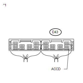
D43-19 (ACCD) - Body ground |
Engine switch off |
Below 1 V |
|
D43-19 (ACCD) - Body ground |
Engine switch on (IG) |
Output voltage at terminal AM21 or AM22 -2 V or more |
|
*1 |
Components with harness connected (Power Management Control ECU) |
| OK | |
REPLACE MAIN BODY ECU (DRIVER SIDE JUNCTION BLOCK ASSEMBLY) |
| NG | |
REPLACE POWER MANAGEMENT CONTROL ECU |
 Power Source Mode does not Change to ON (IG)
DESCRIPTION
When the engine switch is pushed with the electrical key in the cabin, the power
management control ECU receives signals to change the power source mode.
HINT:
To allow use of the Tec ...

Other materials about Toyota Venza:
Precaution
PRECAUTION
1. TROUBLESHOOTING PRECAUTION
NOTICE:
Be sure to read the supplemental restraint system precautions thoroughly
before servicing the brake system (See page
).
Care must be taken to replace each part properly as it could affect ...
Height Control Sensor Data Out of Range When Initializing (B2452)
DESCRIPTION
The headlight leveling ECU assembly stores this DTC if the sensor value received
from the height control sensor is out of range when performing initialization of
the headlight leveling ECU assembly; for example, the vehicle is not level or bei ...
Back Door Entry Unlock Function does not Operate
DESCRIPTION
If the entry back door open function does not operate but the back door entry
lock function operates, the communication between the vehicle and key is normal.
As a faulty part, the back door open switch circuit (from the back door opener switc ...

0.1207