Toyota Venza: Power Mirror Control System(w/o Memory)
Parts Location
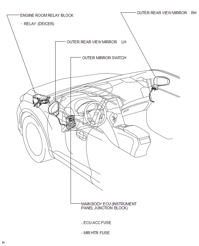
PARTS LOCATION
ILLUSTRATION
Problem Symptoms Table
PROBLEM SYMPTOMS TABLE
HINT:
Use the table below to help determine the cause of problem symptoms. If multiple suspected areas are listed, the potential causes of the symptoms are listed in order of probability in the "Suspected Area" column of the table. Check each symptom by checking the suspected areas in the order they are listed. Replace parts as necessary.
Power Mirror Control System|
Symptom |
Suspected Area |
See page |
|---|---|---|
|
Mirror does not operate |
ECU-ACC fuse |
|
|
Outer mirror switch |
|
|
|
Outer rear view mirror |
|
|
|
Wire harness |
- |
|
|
Mirror heater does not operate* |
MIR HTR fuse |
|
|
DEICER Relay |
- |
|
|
Wire harness |
- |
|
|
Windshield deicer system |
|
.gif)
*: w/ Mirror Heater
 Wireless-linked Return Function does not Operate
DESCRIPTION
When the vehicle doors are unlocked through wireless unlock or entry unlock*1
operation, the certification ECU (smart key ECU assembly)*1 or main body ECU (driver
side junction block ...

Other materials about Toyota Venza:
Lost Communication with AFS LIN (B124D)
DESCRIPTION
Refer to DTC B124D (Lighting system) (See page
).
DTC No.
DTC Detection Condition
Trouble Area
B124D
Malfunctions in LIN communication system
Inner rear view mir ...
Problem Symptoms Table
PROBLEM SYMPTOMS TABLE
HINT:
Use the table below to help determine the cause of problem symptoms.
If multiple suspected areas are listed, the potential causes of the symptoms
are listed in order of probability in the "Suspected Area" ...
Erasing the entire HomeLink® memory (all three programs)
Press and hold the 2 outside buttons for 10 seconds (or 20 seconds depending
on the model) until the indicator light flashes.
If you sell your vehicle, be sure to erase the programs stored in the HomeLink®
memory.
- Before programming
• Insta ...

0.1324