Toyota Venza: Wireless-linked Return Function does not Operate
DESCRIPTION
When the vehicle doors are unlocked through wireless unlock or entry unlock*1 operation, the certification ECU (smart key ECU assembly)*1 or main body ECU (driver side junction block assembly) sends the key ID signal and memory call request signal to the main body ECU (driver side junction block assembly). When the main body ECU (driver side junction block assembly) receives the signal and the driver door is opened, the ECU sends the memory call command signal for the received key ID to each outer mirror control ECU assembly. On receiving the memory call command signal, each outer mirror control ECU assembly moves the mirror surface to the stored position.
- *1: Smart Key System
PROCEDURE
|
1. |
CHECK MEMORY CALL FUNCTION (MEMORY REGISTRATION) |
(a) Connect the Techstream to the DLC3.
(b) Turn the ignition switch ON.
(c) Turn the Techstream on.
(d) Enter the following menus: Body Electrical / Main Body / Data List.
(e) After performing any of the following procedures to link the key and a switch, check the Data List to confirm that the key and switch have been linked.
(f) With the ignition switch off and the driver side door closed, press and hold the M1 or M2 switch. The main body ECU (driver side junction block assembly) will enter electrical key transmitter sub-assembly or door control transmitter assembly recognition code registration mode to allow a key to be linked to mirror surface memory position.
HINT:
If the memory switch is released before entering registration mode, the memory switch will not enter registration mode.
(g) When the manual door lock switch is pressed, check that the buzzer of the front power seat switch LH sounds once (0.5 seconds).
Main Body|
Tester Display |
Measurement Item/Range |
Normal Condition |
Diagnostic Note |
|---|---|---|---|
|
Mem SW No. w/KeyID1 |
Switch linked with key ID1 / NONE, MEM SW1, MEM SW2, or MEM SW3* |
NONE: No switches linked with key ID1 MEM SW1: M1 linked with key ID1 MEM SW2: M2 linked with key ID1 MEM SW3: M3 linked with key ID1* |
- |
|
Mem SW No. w/KeyID2 |
Switch linked with key ID2 / NONE, MEM SW1, MEM SW2, or MEM SW3* |
NONE: No switches linked with key ID2 MEM SW1: M1 linked with key ID2 MEM SW2: M2 linked with key ID2 MEM SW3: M3 linked with key ID2* |
- |
|
Mem SW No. w/KeyID3 |
Switch linked with key ID3 / NONE, MEM SW1, MEM SW2, or MEM SW3* |
NONE: No switches linked with key ID3 MEM SW1: M1 linked with key ID3 MEM SW2: M2 linked with key ID3 MEM SW3: M3 linked with key ID3* |
- |
|
Mem SW No. w/KeyID4 |
Switch linked with key ID4 / NONE, MEM SW1, MEM SW2, or MEM SW3* |
NONE: No switches linked with key ID4 MEM SW1: M1 linked with key ID4 MEM SW2: M2 linked with key ID4 MEM SW3: M3 linked with key ID4* |
- |
|
Mem SW No. w/KeyID5 |
Switch linked with key ID5 / NONE, MEM SW1, MEM SW2, or MEM SW3* |
NONE: No switches linked with key ID5 MEM SW1: M1 linked with key ID5 MEM SW2: M2 linked with key ID5 MEM SW3: M3 linked with key ID5* |
- |
|
Mem SW No. w/KeyID6 |
Switch linked with key ID6 / NONE, MEM SW1, MEM SW2, or MEM SW3* |
NONE: No switches linked with key ID6 MEM SW1: M1 linked with key ID6 MEM SW2: M2 linked with key ID6 MEM SW3: M3 linked with key ID6* |
- |
|
Mem SW No. w/KeyID7 |
Switch linked with key ID7 / NONE, MEM SW1, MEM SW2, or MEM SW3* |
NONE: No switches linked with key ID7 MEM SW1: M1 linked with key ID7 MEM SW2: M2 linked with key ID7 MEM SW3: M3 linked with key ID7* |
- |
- *: Although the item is displayed on the Techstream, it is not applicable to this vehicle.
OK:
The Data List shows that the key ID has been linked to a switch (M1 or M2).
| NG | .gif) |
GO TO OTHER DIAGNOSIS PROCEDURE (Wireless Transmitter Memory Function does not Operate) |
|
.gif)
|
2. |
CHECK MEMORY CALL FUNCTION |
(a) Perform a wireless door unlock operation and check that opening the driver side door causes the following:
- The buzzer sounds for 0.1 seconds.
- The mirror surface position automatically moves to a stored position.
|
Result |
Proceed to |
|---|---|
|
The memory call function does not operate together with wireless door unlock operation only. |
A |
|
The memory call function does not operate together with entry unlock operation only.* |
B |
|
The memory call function does not operate at all. |
C |
- *: w/ Smart Key System
| B | |
GO TO STEP 10 |
| C | |
GO TO STEP 17 |
|
|
3. |
CHECK WIRELESS DOOR LOCK CONTROL FUNCTIONS |
(a) Check wireless door lock control operation (w/ Smart Key System) (See page
.gif) )
)
(b) Check wireless door lock control operation (w/o Smart Key System) (See page
).
|
Result |
Proceed to |
|---|---|
|
Wireless door lock control operation is normal |
A |
|
Wireless door lock control operation (w/ Smart Key System) is not normal |
B |
|
Wireless door lock control operation (w/o Smart Key System) is not normal |
C |
| B | |
GO TO WIRELESS DOOR LOCK CONTROL SYSTEM (w/ Smart Key System) (PROBLEM SYMPTOMS TABLE) |
| C | |
GO TO WIRELESS DOOR LOCK CONTROL SYSTEM (w/o Smart Key System) |
|
|
4. |
CHECK MEMORY AND SEAT RESTORING OPERATION (POWER SEAT CONTROL SYSTEM) |
(a) Check memory and seat restoring operation (See page
).
OK:
Memory and seat restoring operations are normal.
| NG | |
GO TO STEP 7 |
|
|
5. |
REPLACE OUTER MIRROR CONTROL ECU ASSEMBLY |
(a) Replace the outer mirror control ECU assembly (driver door) and outer mirror
control ECU assembly (front passenger door) (See page
).
|
|
6. |
CHECK MEMORY CALL FUNCTION |
(a) Perform registration for memory call function (See page
).
(b) Perform a wireless door unlock operation and check that opening the driver side door causes the following:
- The buzzer sounds for 0.1 seconds.
- The mirror surface position automatically moves to a stored position.
OK:
Memory call function is normal.
| OK | |
END (OUTER MIRROR CONTROL ECU ASSEMBLY WAS DEFECTIVE) |
| NG | |
REPLACE MAIN BODY ECU (DRIVER SIDE JUNCTION BLOCK ASSEMBLY) |
|
7. |
READ VALUE USING TECHSTREAM (DOOR COURTESY SWITCH) |
(a) Connect the Techstream to the DLC3.
(b) Turn the ignition switch ON.
(c) Turn the Techstream on.
(d) Enter the following menus: Body Electrical / Main Body / Data List.
(e) Read the Data List according to the display on the Techstream.
Main Body|
Tester Display |
Measurement Item/Range |
Normal Condition |
Diagnostic Note |
|---|---|---|---|
|
D Door Courtesy SW |
Driver door courtesy switch condition/ON or OFF |
ON: Door courtesy switch on (driver door open) OFF: Door courtesy switch off (driver door closed) |
- |
OK:
ON or OFF appears on the Techstream.
|
Result |
Proceed to |
|---|---|
|
OK (w/ Smart Key System) |
A |
|
OK (w/o Smart Key System) |
B |
|
NG |
C |
| B | |
REPLACE MAIN BODY ECU (DRIVER SIDE JUNCTION BLOCK ASSEMBLY) |
| C | |
GO TO LIGHTING SYSTEM (Door Courtesy Switch Circuit) |
|
|
8. |
REPLACE MAIN BODY ECU (DRIVER SIDE JUNCTION BLOCK ASSEMBLY) |
(a) Replace the main body ECU (driver side junction block assembly) (See page
).
|
|
9. |
CHECK MEMORY CALL FUNCTION |
(a) Perform a wireless door unlock operation and check that opening the driver side door causes the following:
- The buzzer sounds for 0.1 seconds.
- The mirror surface position automatically moves to a stored position.
OK:
Memory call function is normal.
| OK | |
END (MAIN BODY ECU (DRIVER SIDE JUNCTION BLOCK ASSEMBLY) WAS DEFECTIVE) |
| NG | |
REPLACE CERTIFICATION ECU (SMART KEY ECU ASSEMBLY) |
|
10. |
CHECK SMART KEY SYSTEM (ENTRY FUNCTION) |
(a) Check the smart key system operation (See page
).
OK:
Smart key system operation is normal.
| NG | |
GO TO SMART KEY SYSTEM (PROBLEM SYMPTOMS TABLE) |
|
|
11. |
CHECK MEMORY AND SEAT RESTORING OPERATION (POWER SEAT CONTROL SYSTEM) |
(a) Check memory and seat restoring operation (See page
).
OK:
Memory and seat restoring operation is normal.
| NG | |
GO TO STEP 14 |
|
|
12. |
REPLACE OUTER MIRROR CONTROL ECU ASSEMBLY |
(a) Replace the outer mirror control ECU assembly (driver door) and outer mirror
control ECU assembly (front passenger door) (See page
).
|
|
13. |
CHECK MEMORY CALL FUNCTION |
(a) Perform registration for memory call function (See page
).
(b) Perform a wireless door unlock operation and check that opening the driver side door causes the following:
- The buzzer sounds for 0.1 seconds.
- The mirror surface position automatically moves to a stored position.
OK:
Memory call function is normal.
| OK | |
END (OUTER MIRROR CONTROL ECU ASSEMBLY WAS DEFECTIVE) |
| NG | |
REPLACE MAIN BODY ECU (DRIVER SIDE JUNCTION BLOCK ASSEMBLY) |
|
14. |
READ VALUE USING TECHSTREAM (DOOR COURTESY SWITCH) |
(a) Connect the Techstream to the DLC3.
(b) Turn the ignition switch ON.
(c) Turn the Techstream on.
(d) Enter the following menus: Body Electrical / Main Body / Data List.
(e) Read the Data List according to the display on the Techstream.
Main Body|
Tester Display |
Measurement Item/Range |
Normal Condition |
Diagnostic Note |
|---|---|---|---|
|
D Door Courtesy SW |
Driver door courtesy switch condition/ON or OFF |
ON: Door courtesy switch on (driver door open) OFF: Door courtesy switch off (driver door closed) |
- |
OK:
ON or OFF appears on the Techstream.
|
Result |
Proceed to |
|---|---|
|
OK (w/ Smart Key System) |
A |
|
OK (w/o Smart Key System) |
B |
|
NG |
C |
| B | |
REPLACE MAIN BODY ECU (DRIVER SIDE JUNCTION BLOCK ASSEMBLY) |
| C | |
GO TO LIGHTING SYSTEM (Door Courtesy Switch Circuit) |
|
|
15. |
REPLACE MAIN BODY ECU (DRIVER SIDE JUNCTION BLOCK ASSEMBLY) |
(a) Replace the main body ECU (driver side junction block assembly) (See page
).
|
|
16. |
CHECK MEMORY CALL FUNCTION |
(a) Perform registration for memory call function (See page
).
(b) Perform a wireless door unlock operation and check that opening the driver side door causes the following:
- The buzzer sounds for 0.1 seconds.
- The mirror surface position automatically moves to a stored position.
OK:
Memory call function is normal.
| OK | |
END (MAIN BODY ECU (DRIVER SIDE JUNCTION BLOCK ASSEMBLY) WAS DEFECTIVE) |
| NG | |
REPLACE CERTIFICATION ECU (SMART KEY ECU ASSEMBLY) |
|
17. |
CHECK MEMORY CALL FUNCTION |
(a) Perform a wireless door unlock operation and check that opening the driver side door causes the following:
- The buzzer sounds for 0.1 seconds.
- The mirror surface position automatically moves to a stored position.
OK:
Memory call function is normal.
| NG | |
GO TO STEP 21 |
|
|
18. |
CHECK REACTIVATION FUNCTION |
|
(a) Turn the ignition switch ON. |
|
.png)
(b) Using the outer mirror switch assembly, turn the mirror surface to the fully left position.
Text in Illustration|
*a |
Turn to Left Fully |
(c) Press the M1 switch while the SET switch is being pressed.
(d) Check that the buzzer sounds for 0.5 seconds and the mirror surface position is memorized.
|
(e) Using the outer mirror switch assembly, turn the mirror surface to the fully right position. Text in Illustration
|
|
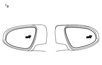
(f) Press the M1 switch.
(g) Check that the buzzer sounds for 0.1 seconds and the outer mirror automatically moves to the recorded fully left position.
OK:
Mirror function is normal.
| NG | |
GO TO STEP 24 |
|
|
19. |
REPLACE OUTER MIRROR CONTROL ECU ASSEMBLY |
(a) Replace the outer mirror control ECU assembly (driver door) and outer mirror
control ECU assembly (front passenger door) (See page
).
|
|
20. |
CHECK MEMORY CALL FUNCTION |
(a) Perform registration for memory call function (See page
).
(b) Perform a wireless door unlock operation and check that opening the driver side door causes the following:
- The buzzer sounds for 0.1 seconds.
- The mirror surface position automatically moves to a stored position.
OK:
Memory call function is normal.
| OK | |
END (OUTER MIRROR CONTROL ECU ASSEMBLY WAS DEFECTIVE) |
| NG | |
REPLACE MAIN BODY ECU (DRIVER SIDE JUNCTION BLOCK ASSEMBLY) |
|
21. |
READ VALUE USING TECHSTREAM (DOOR COURTESY SWITCH) |
(a) Connect the Techstream to the DLC3.
(b) Turn the ignition switch ON.
(c) Turn the Techstream on.
(d) Enter the following menus: Body Electrical / Main Body / Data List.
(e) Read the Data List according to the display on the Techstream.
Main Body|
Tester Display |
Measurement Item/Range |
Normal Condition |
Diagnostic Note |
|---|---|---|---|
|
D Door Courtesy SW |
Driver door courtesy switch condition/ON or OFF |
ON: Door courtesy switch on (driver door open) OFF: Door courtesy switch off (driver door closed) |
- |
OK:
ON or OFF appears on the Techstream.
|
Result |
Proceed to |
|---|---|
|
OK (w/ Smart Key System) |
A |
|
OK (w/o Smart Key System) |
B |
|
NG |
C |
| B | |
REPLACE MAIN BODY ECU (DRIVER SIDE JUNCTION BLOCK ASSEMBLY) |
| C | |
GO TO LIGHTING SYSTEM (Door Courtesy Switch Circuit) |
|
|
22. |
REPLACE MAIN BODY ECU (DRIVER SIDE JUNCTION BLOCK ASSEMBLY) |
(a) Replace the main body ECU (driver side junction block assembly) (See page
).
|
|
23. |
CHECK MEMORY CALL FUNCTION |
(a) Perform registration for memory call function (See page
).
(b) Perform a wireless door unlock operation and check that opening the driver side door causes the following:
- The buzzer sounds for 0.1 seconds.
- The mirror surface position automatically moves to a stored position.
OK:
Memory call function is normal.
| OK | |
END (MAIN BODY ECU (DRIVER SIDE JUNCTION BLOCK ASSEMBLY) WAS DEFECTIVE) |
| NG | |
REPLACE CERTIFICATION ECU (SMART KEY ECU ASSEMBLY) |
|
24. |
CHECK ELECTRICAL REMOTE CONTROL MIRROR FUNCTION |
(a) Check electrical remote control mirror function (See page
).
OK:
Electrical remote control mirror function is normal.
| OK | |
REPLACE OUTER MIRROR CONTROL ECU ASSEMBLY |
| NG | |
GO TO OTHER DIAGNOSIS PROCEDURE (PROBLEM SYMPTOMS TABLE) |
 Wireless Transmitter Memory Function does not Operate
DESCRIPTION
Key IDs can be registered (linked) with either the M1 or M2 seat memory switches.
The key ID registration procedure should be performed while the electrical key transmitter
sub-assemb ...
 Power Mirror Control System(w/o Memory)
Parts Location
PARTS LOCATION
ILLUSTRATION
Problem Symptoms Table
PROBLEM SYMPTOMS TABLE
HINT:
Use the table below to help determine the cause of problem symptoms. If multiple
suspected ...
Other materials about Toyota Venza:
Inspection
INSPECTION
PROCEDURE
1. INSPECT FRONT DRIVE SHAFT ASSEMBLY
(a) Check whether the drive shaft dimensions are within the following
specifications.
Text in Illustration
*A
LH
*B
...
LVL Terminal Circuit
DESCRIPTION
By connecting terminals LVL and CG of the DLC3, the headlight leveling
ECU assembly initializes the height control sensor signal.
WIRING DIAGRAM
PROCEDURE
1.
CHECK HARNESS AND CONNECTOR (DLC3 - HEADLIGH ...
Dtc Check / Clear
DTC CHECK / CLEAR
1. CHECK DTC
(a) Connect the Techstream to the DLC3.
(b) Turn the engine switch on (IG).
(c) Turn the clearance sonar main switch on.
(d) Turn the Techstream on.
(e) Enter the following menus: Body Electrical / Intuitive P/A / DTC.
(f) ...

0.1231