Toyota Venza: 4wd Control Ecu
Components
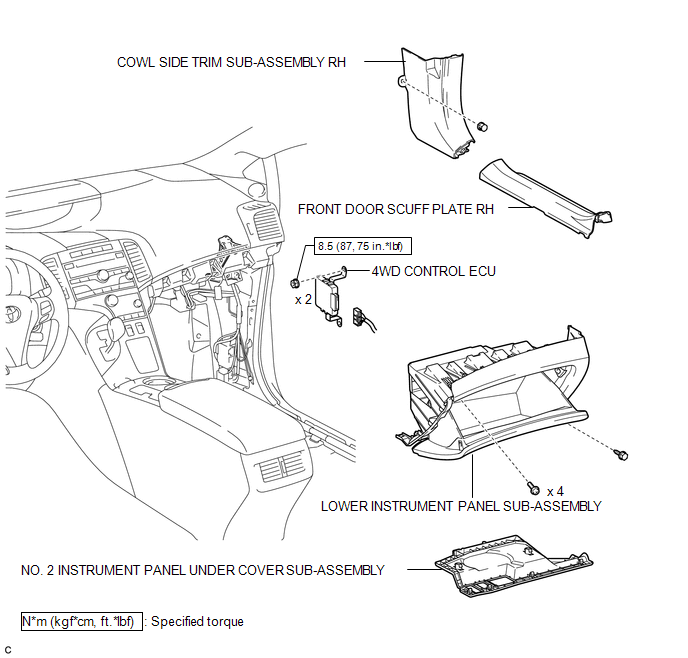
COMPONENTS
ILLUSTRATION
Removal
REMOVAL
PROCEDURE
1. REMOVE FRONT DOOR SCUFF PLATE RH
2. REMOVE COWL SIDE TRIM SUB-ASSEMBLY RH
3. REMOVE NO. 2 INSTRUMENT PANEL UNDER COVER SUB-ASSEMBLY
4. REMOVE LOWER INSTRUMENT PANEL SUB-ASSEMBLY
.gif)
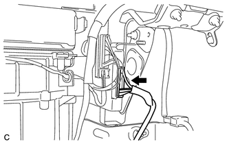
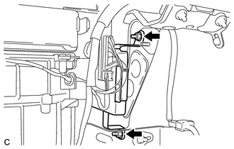
5. REMOVE 4WD CONTROL ECU
|
(a) Disconnect the connector. |
|
|
(b) Remove the 2 nuts and ECU. |
|
Installation
INSTALLATION
PROCEDURE
1. INSTALL 4WD CONTROL ECU
|
(a) Install the ECU with the 2 nuts. Torque: 8.5 N·m {87 kgf·cm, 75 in·lbf} |
|
.png)
|
(b) Connect the connector. |
|
.png)
2. INSTALL LOWER INSTRUMENT PANEL SUB-ASSEMBLY
.gif)
3. INSTALL NO. 2 INSTRUMENT PANEL UNDER COVER SUB-ASSEMBLY
4. INSTALL COWL SIDE TRIM SUB-ASSEMBLY RH
5. INSTALL FRONT DOOR SCUFF PLATE RH


Other materials about Toyota Venza:
Security Horn Circuit
DESCRIPTION
When the theft deterrent system is switched from the armed state to the alarm
sounding state, the main body ECU (driver side junction block assembly) controls
the security horn.
WIRING DIAGRAM
PROCEDURE
1.
PERFORM A ...
Monitor Drive Pattern
MONITOR DRIVE PATTERN
1. TEST MONITOR DRIVE PATTERN FOR ECT
CAUTION:
Perform this drive pattern on a level surface and strictly observe the posted
speed limits and traffic laws while driving.
HINT:
Performing this drive pattern is one method to simulate ...
Removal
REMOVAL
CAUTION / NOTICE / HINT
HINT:
Use the same procedure for the LH side and RH side.
The following procedure is for the LH side.
PROCEDURE
1. REMOVE ENGINE ASSEMBLY WITH TRANSAXLE (for 2GR-FE)
HINT:
Refer to the procedure up to Re ...

0.1429