Toyota Venza: Inspection
INSPECTION
PROCEDURE
1. INSPECT TIE ROD ASSEMBLY LH
|
(a) Secure the tie rod assembly LH in a vise. |
|
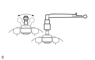
(b) Install the nut to the stud bolt.
(c) Flip the ball joint back and forth 5 times.
(d) Set a torque wrench to the nut, turn the ball joint continuously at a rate of 2 to 4 seconds per turn, and check the turning torque on the 5th turn.
Standard turning torque:
0.49 to 3.43 N*m (5.0 to 35.0 kgf*cm, 4.3 to 30.3 in.*lbf)
HINT:
If the turning torque is not within the specified range, replace the tie rod assembly LH.
2. INSPECT TIE ROD ASSEMBLY RH
HINT:
Perform the same procedure as for the LH side.
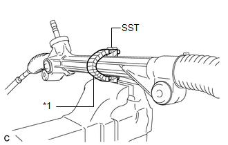
3. INSPECT TOTAL PRELOAD
|
(a) Using SST, secure the steering link assembly in a vise. SST: 09612-00012 Text in Illustration
HINT: Tape SST before use. |
|
|
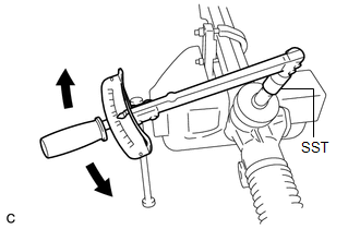
(b) Using SST and a torque wrench, inspect the total preload. SST: 09616-00020 Standard preload: 0.7 to 1.0 N*m (7.0 to 10.7 kgf*cm, 5.8 to 9.2 in.*lbf) NOTICE: Inspect the total preload around the steering rack center position. HINT: If the total preload is not within the specified range, replace the steering gear assembly with a new one. |
|
 Disassembly
DISASSEMBLY
PROCEDURE
1. REMOVE STEERING RACK BOOT CLIP (for LH Side)
(a) Using pliers, remove the steering rack boot clip.
2. REMOVE STEERING RACK BOOT CLIP (for RH Side)
HINT:
Perform the same ...
 Installation
INSTALLATION
CAUTION / NOTICE / HINT
NOTICE:
When disconnecting the steering intermediate shaft assembly and pinion shaft
of steering gear assembly, be sure to place matchmarks before servicing.
...
Other materials about Toyota Venza:
Lost Communication with Gateway Module (MS Bus) (U1002)
DESCRIPTION
The main body ECU will store this DTC when no signals can be received
from the ECUs that have been memorized as those that are connected to the
CAN MS bus.
When the main body ECU receives a response signal from the ECUs connecte ...
Terminals Of Ecu
TERMINALS OF ECU
1. CHECK SLIDING ROOF ECU (SLIDING ROOF DRIVE GEAR SUB-ASSEMBLY)
(a) Disconnect the P4 ECU connector.
(b) Measure the resistance and voltage according to the value(s) in the table
below.
HINT:
Measure the values on the wire harness si ...
Inner Rear View Mirror Power Source Circuit
DESCRIPTION
This circuit detects the state of the ignition switch, and sends it to the inner
rear view mirror assembly.
WIRING DIAGRAM
CAUTION / NOTICE / HINT
NOTICE:
Inspect the fuses for circuits related to this system before performing the followin ...

0.1158