Toyota Venza: Removal
REMOVAL
PROCEDURE
1. REMOVE REAR SEAT HEADREST ASSEMBLY
.gif)
2. REMOVE REAR SEAT CENTER HEADREST ASSEMBLY
3. REMOVE REAR SEAT INNER TRACK BRACKET COVER
4. REMOVE REAR SEAT OUTER TRACK BRACKET COVER
5. DISCONNECT REAR SEAT RECLINING CONTROL CABLE SUB-ASSEMBLY
6. REMOVE REAR SEAT ASSEMBLY RH
7. REMOVE SEAT ADJUSTER COVER CAP RH
8. REMOVE REAR SEAT RECLINING RELEASE LEVER RH
9. REMOVE REAR SEAT RECLINING COVER RH
10. REMOVE CENTER SEAT HINGE COVER RH
11. REMOVE REAR SEAT INNER RECLINING COVER RH
12. REMOVE REAR SEAT CENTER ARMREST ASSEMBLY
13. REMOVE REAR SEAT CUSHION COVER WITH PAD
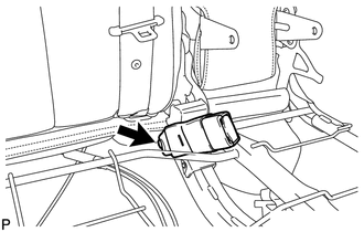
14. REMOVE REAR SEAT INNER BELT ASSEMBLY RH
|
(a) Remove the bolt and the rear seat inner belt assembly RH. |
|
 Components
COMPONENTS
ILLUSTRATION
ILLUSTRATION
...
 Installation
INSTALLATION
PROCEDURE
1. INSTALL REAR SEAT INNER BELT ASSEMBLY RH
(a) Install the rear seat inner belt assembly RH with the bolt.
Torque:
42 N·m {428 kgf·cm, 31 ft·lbf}
...
Other materials about Toyota Venza:
Lost Communication with Rear Airbag Sensor LH (B1637/82,B1638/82,B1647/82,B1697/82,B1698/82)
DESCRIPTION
The side collision sensor LH circuit (to determine deployment of the front seat
side airbag assembly LH and curtain shield airbag assembly LH) is composed of the
center airbag sensor assembly, rear airbag sensor LH and side airbag sensor LH.
...
Short in Driver Side Squib Circuit (B1800/51-B1803/51)
DESCRIPTION
The driver side squib circuit consists of the center airbag sensor assembly,
spiral cable and steering pad.
The center airbag sensor assembly uses this circuit to deploy the airbag when
deployment conditions are met.
These DTCs are stored wh ...
Inspection
INSPECTION
PROCEDURE
1. INSPECT FRONT POWER SEAT SWITCH LH (w/o Seat Position Memory System)
(a) Measure the resistance between the terminals when each switch is
operated.
Standard Resistance:
Slide Switch
Tester Co ...

0.1685