Toyota Venza: Parts Location
PARTS LOCATION
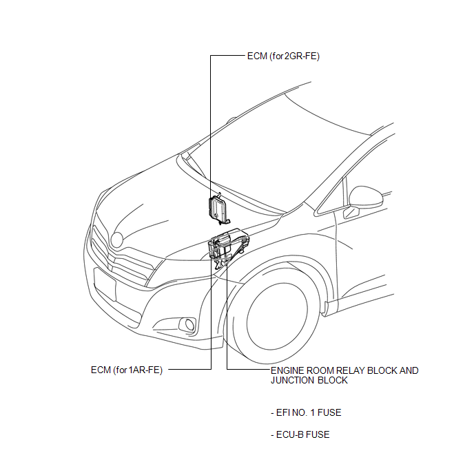
ILLUSTRATION
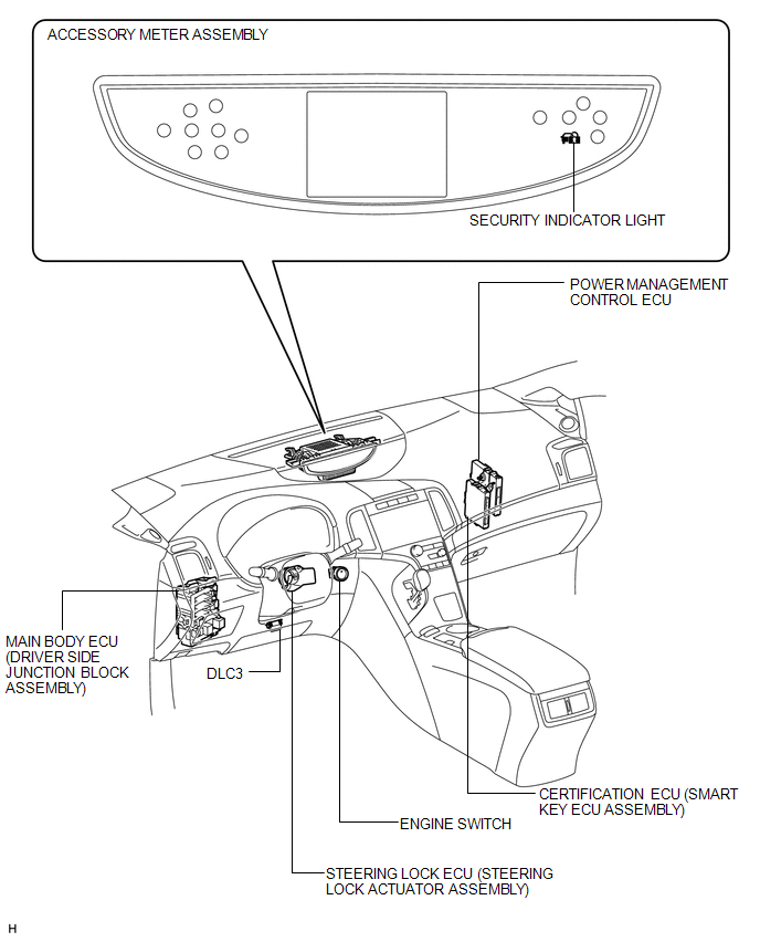
ILLUSTRATION

 Precaution
PRECAUTION
1. PRECAUTION FOR DISCONNECTING CABLE FROM NEGATIVE BATTERY TERMINAL
NOTICE:
When disconnecting the cable from the negative (-) battery terminal, initialize
the following system after ...
Other materials about Toyota Venza:
Problem Symptoms Table
PROBLEM SYMPTOMS TABLE
HINT:
Use the table below to help determine the cause of problem symptoms. If multiple
suspected areas are listed, the potential causes of the symptoms are listed in order
of probability in the "Suspected Area" column of ...
Fuel pump shut off system
To minimize the risk of fuel leakage when the engine stalls or an airbag inflates
upon collision, the fuel pump shut off system stops supplying fuel to the engine.
Follow the procedure below to restart the engine after the system is activated.
►Vehic ...
Inspection
INSPECTION
PROCEDURE
1. INSPECT ENGINE SWITCH
(a) Measure the resistance according to the value(s) in the table below.
Standard Resistance:
Tester Connection
Switch Condition
Specified Condition
7 (SS1) ...

0.1155