Toyota Venza: Parts Location
PARTS LOCATION
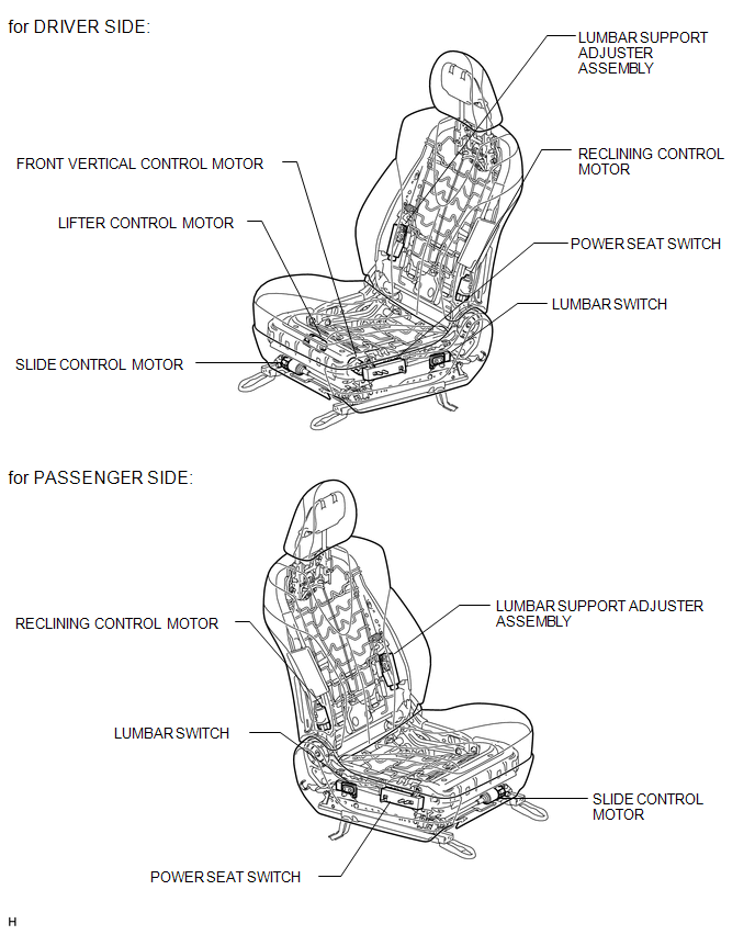
ILLUSTRATION
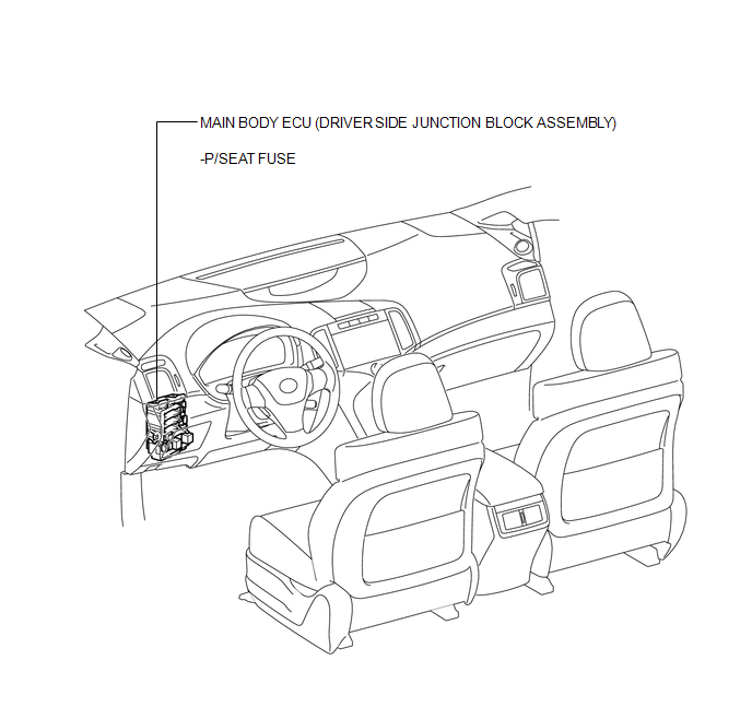
ILLUSTRATION
 Precaution
PRECAUTION
1. NOTICE FOR INITIALIZATION
HINT:
When disconnecting the cable from the negative (-) battery terminal, initialize
the following systems after the cable is reconnected.
Sys ...
 System Description
SYSTEM DESCRIPTION
1. FRONT POWER SEAT CONTROL SYSTEM DESCRIPTION
The driver seat is equipped with slide, reclining, lifter, front vertical and
lumbar support adjustment functions.
2. FUNCTION OF ...
Other materials about Toyota Venza:
Front Stabilizer Bar(for 2gr-fe 2wd)
Components
COMPONENTS
ILLUSTRATION
Removal
REMOVAL
PROCEDURE
1. REMOVE FRONT FRAME ASSEMBLY (When Using the Engine Support Bridge)
(See page )
2. REMOVE ENGINE ASSEMBLY WITH TRANSAXLE (When Not Using the Engine Support Bridge)
(See page )
3. ...
Freeze Frame Data
FREEZE FRAME DATA
1. FREEZE FRAME DATA
NOTICE:
Freeze frame data values will vary depending on the measurement conditions,
surroundings, or vehicle conditions. For this reason, there may be a problem
even when the values are within specifica ...
Security Indicator Light Circuit
DESCRIPTION
The security indicator light blinks continuously due to a continuous signal received
from the certification ECU (smart key ECU assembly) while the engine immobiliser
is set.
WIRING DIAGRAM
CAUTION / NOTICE / HINT
NOTICE:
If the certifica ...

0.1737