Toyota Venza: Parts Location
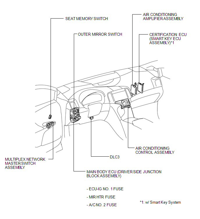
PARTS LOCATION
ILLUSTRATION
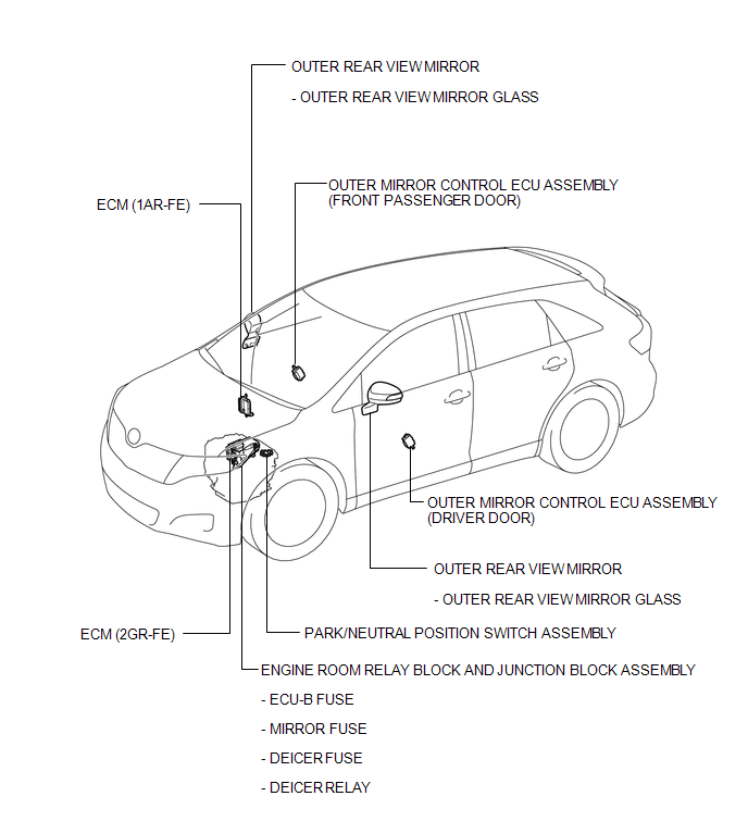
ILLUSTRATION
 Precaution
PRECAUTION
1. PRECAUTION FOR DISCONNECTING CABLE FROM NEGATIVE BATTERY TERMINAL
NOTICE:
When disconnecting the cable from the negative (-) battery terminal, initialize
the following system after ...
 System Description
SYSTEM DESCRIPTION
1. POWER MIRROR CONTROL SYSTEM DESCRIPTION
(a) This system has the following functions: power retract mirror function*,
reverse shift-linked function, electrical remote control ...
Other materials about Toyota Venza:
Removal
REMOVAL
CAUTION / NOTICE / HINT
NOTICE:
When disconnecting the steering intermediate shaft assembly and pinion shaft
of the steering gear assembly, be sure to place matchmarks before servicing.
PROCEDURE
1. PLACE FRONT WHEELS FACING STRAIGHT AHEAD
2. S ...
Adjustment
ADJUSTMENT
PROCEDURE
1. PRECAUTIONS AND WORK DESCRIPTION
(a) The U660E automatic transaxle does not have an oil filler tube and oil level
gauge. When adding fluid, add fluid through the refill hole on the transaxle case.
The fluid level can be adjusted ...
Outer Rear View Mirror Glass
Components
COMPONENTS
ILLUSTRATION
Inspection
INSPECTION
PROCEDURE
1. INSPECT OUTER MIRROR RH
(a) Check the outer mirror heater operation.
(1) Measure the resistance according to the value(s) in the table below.
Standard Resistanc ...

0.1309