Toyota Venza: Parts Location
PARTS LOCATION
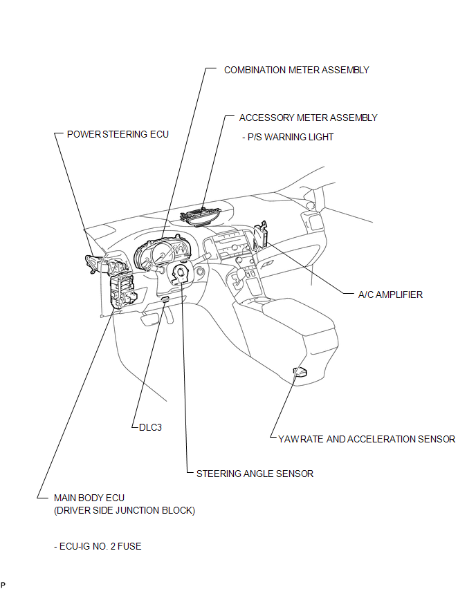
ILLUSTRATION
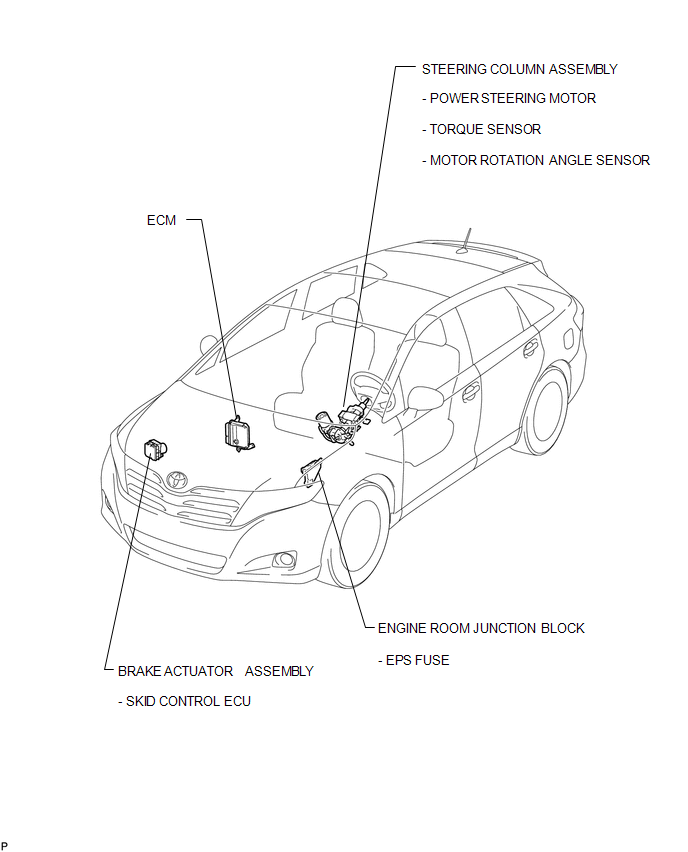
ILLUSTRATION

 Precaution
PRECAUTION
1. PRECAUTION FOR DISCONNECTING THE BATTERY CABLE
NOTICE:
When disconnecting the cable from the negative (-) battery terminal, initialize
the following systems after the cable is recon ...
Other materials about Toyota Venza:
Back Door Entry Lock Function does not Operate
DESCRIPTION
If the back door entry lock function does not operate but the back door open
function operates, the communication between the vehicle and key is normal. As a
faulty part, the entry lock switch circuit (from the back door opener switch assembly ...
System Diagram
SYSTEM DIAGRAM
Input and Output Signal of Each ECU
Transmitting ECU (transmitter)
Receiving ECU
Signal
Communication Method
Power management Control ECU
Steering Lock ECU (Steering Lock ...
Lost Communication with A/C ECU (U0164)
DESCRIPTION
DTC No.
DTC Detection Condition
Trouble Area
U0164
No communication from the air conditioning amplifier continues.
Air conditioning amplifier branch wire or connect ...

0.1613