Toyota Venza: Parts Location
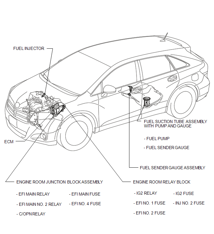
PARTS LOCATION
ILLUSTRATION
 Precaution
PRECAUTION
1. BEFORE WORKING ON FUEL SYSTEM
(a) When disconnecting a fuel line, fuel will splash. So observe the following
precautions:
(1) Do not smoke or work near fire when handling the fuel s ...
 On-vehicle Inspection
ON-VEHICLE INSPECTION
PROCEDURE
1. CHECK FOR FUEL PUMP OPERATION AND INSPECT FOR FUEL LEAK
(a) Check fuel pump operation.
(1) Connect the Techstream to the DLC3.
(2) Turn the ignition switch to O ...
Other materials about Toyota Venza:
Installation
INSTALLATION
PROCEDURE
1. INSTALL THERMOSTAT
(a) Install a new gasket to the thermostat.
(b) Install the thermostat with the jiggle valve facing upward.
HINT:
The jiggle valve may be set to within 10° on either side of the prescribed
...
Removal
REMOVAL
PROCEDURE
1. REMOVE REAR BUMPER PLATE LH
(a) Using a screwdriver with the tip wrapped with protective tape, disengage
the 2 claws and remove the rear bumper plate LH.
Text in Illustration
*1
Pro ...
HD Radio Tuner Malfunction (B1551,B158D,B15A0,B15B0,B15B3,B15B4,B15B7)
DESCRIPTION
These DTCs are stored when a malfunction occurs in the radio and display receiver
assembly.
DTC No.
DTC Detection Condition
Trouble Area
B1551
When any of the following conditions is ...

0.1513