Toyota Venza: Precaution
PRECAUTION
1. BEFORE WORKING ON FUEL SYSTEM
(a) When disconnecting a fuel line, fuel will splash. So observe the following precautions:
(1) Do not smoke or work near fire when handling the fuel system.
(2) Keep gasoline away from rubber or leather parts.
(3) Perform the Discharge Fuel System Pressure procedure below before disconnecting a fuel line to prevent gasoline from spilling out.
2. DISCHARGE FUEL SYSTEM PRESSURE
CAUTION:
- The Discharge Fuel System Pressure procedure must be performed before disconnecting any part of the fuel system.
- After performing the Discharge Fuel System Pressure procedure, pressure will remain in the fuel lines. When disconnecting a fuel line, cover it with a shop rag or a piece of cloth to prevent fuel from spraying or coming out.
(a) Remove the rear seat assembly LH (See page
.gif) ).
).
(b) Remove the rear seat assembly RH (See page
).
(c) Turn over the rear floor carpet and the rear floor silencer.
(d) Remove the service hole cover and disconnect the fuel pump connector.
.png)
(e) Start the engine.
(f) After the engine has stopped, turn the ignition switch off.
HINT:
DTC P0171/25 (fuel problem) may be detected.
(g) Crank the engine again. Check that the engine does not start.
(h) Remove the fuel tank cap to discharge pressure from the fuel tank.
(i) Reconnect the fuel pump connector.
(j) Install the rear floor service hole cover.
(k) Install the rear floor carpet and the rear floor silencer.
(l) Install the rear seat assembly LH (See page
).
(m) Install the rear seat assembly RH (See page
).
3. FUEL LINE
(a) When disconnecting a high fuel pressure line, a large amount of gasoline will spill out, so perform the following procedure:
(1) Discharge the fuel system pressure (See step 2).
(2) Disconnect the fuel pump tube.
(3) Drain the fuel that remains inside the fuel pump tube.
(4) Cover the disconnected fuel pump tube with a plastic bag to prevent damage and contamination.
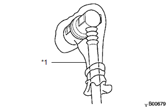 Text in Illustration
|
*1 |
Plastic Bag |
(5) Put a container under the connection part.
(b) Perform the following procedure when disconnecting a fuel tube.
NOTICE:
Do not forcibly bend, kink or twist the fuel tube.
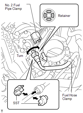
(1) Remove the fuel tube from the fuel hose clamp.
(2) Remove the No. 2 fuel pipe clamp.
(3) Wipe off any dirt on the fuel tube connector.
(4) Hold the fuel tube connector, and then install SST.
SST: 09268-21011
(5) Turn SST to align the retainer inside the fuel tube connector with the chamfered part of SST.
(6) Insert SST into the fuel tube and hold it. Then push the fuel tube connector toward SST.
(7) Mount the retainer of the fuel tube connector onto the chamfered part of SST.
(8) Slide SST and the fuel tube connector together toward the fuel tube until they make a "click" sound, and then disconnect the fuel tube.
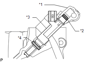
.png) Text in Illustration
Text in Illustration
|
*1 |
O-ring |
|
*2 |
Retainer |
|
*3 |
Nylon Tube |
|
*4 |
Housing |
|
*5 |
Pipe |
(9) Drain the fuel remaining inside the fuel tube.
(10) Cover the fuel tube and fuel pipe with a plastic bag to protect the disconnected part.
(c) Perform the following procedure when connecting a fuel tube connector.
 Text in Illustration
|
*1 |
No. 2 Fuel Pipe Clamp |
|
*2 |
Fuel Hose Clamp |
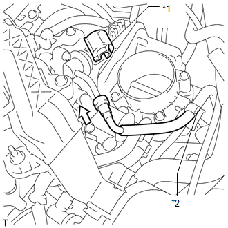
(1) Check if there is any damage or foreign objects on the connecting part of the pipe.
(2) Match the axis of the connector with the axis of the pipe, and push into the connector until the connector makes a "click" sound. If the connection is tight, apply a small amount of clean engine oil to the tip of the pipe.
(3) After finishing the connection, check if the pipe and the connector are securely connected by pulling on them.
(4) Inspect for fuel leaks.
(5) Install a new No. 2 fuel pipe clamp.
(6) Install the fuel tube to the fuel hose clamp.
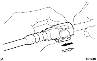
(d) Perform the following procedure when disconnecting a fuel tube connector (quick type A):
(1) Remove the No. 1 fuel pipe clamp from the tube connector.
.png)
(2) Check that there is no dirt or other foreign objects on the pipe and around the connector before disconnecting them. Clean them if necessary.
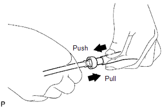
(3) Disconnect the connector from the pipe by hand.
(4) When the connector and the pipe are stuck, push in and pull on the connector to release them. Pull the connector out of the pipe carefully.
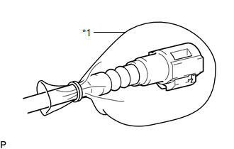
(5) Check that there is no dirt or other foreign objects on the sealing surface of the disconnected pipe. Clean it away if necessary.
(6) Cover the disconnected pipe and connector with a plastic bag to prevent damage and contamination.
 Text in Illustration
|
*1 |
Plastic Bag |
(e) Perform the following procedure when connecting a fuel tube connector (quick type A):
(1) Check if there is any damage or foreign objects on the connecting parts of the pipes.
(2) Line up the two parts of the pipes to be connected, and push them together until the connector makes a "click" sound. If the pipe is difficult to push into the connector, apply a small amount of clean engine oil to the tip of the pipe and reinsert it.
(3) After connecting the pipes, check that the pipe and connector are securely connected by pulling on them.
(4) Inspect for fuel leaks (See page ).
(5) Install the No. 1 fuel pipe clamp to the tube connector.
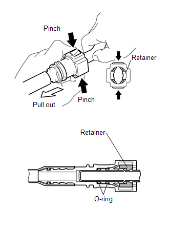
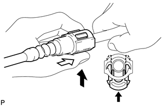
(f) Perform the following procedure when disconnecting a fuel tube connector (quick type B):
 Text in Illustration
|
*1 |
Retainer |
(1) Check that there is no damage or foreign matter on the part of the pipe that contacts the connector.
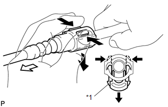
(2) Detach the 2 claws of the connector retainer. Push down on the connector and disconnect it from the pipe.
HINT:
Be sure to disconnect it by hand.
(3) If the connector and pipe are stuck, pinch the fuel pipe by hand, and push and pull the connector to disconnect it.
(4) Check for foreign matter on the seal surface of the disconnected pipe. Clean it if necessary.
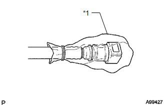
(5) Cover the disconnected pipe and connector with a plastic bag to prevent damage and contamination.
 Text in Illustration
|
*1 |
Plastic Bag |
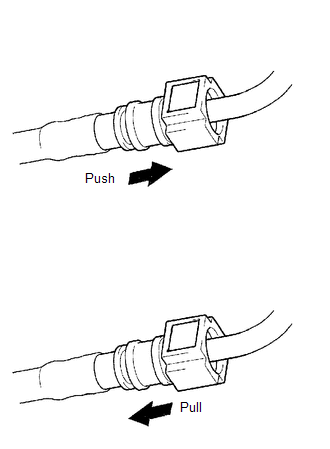
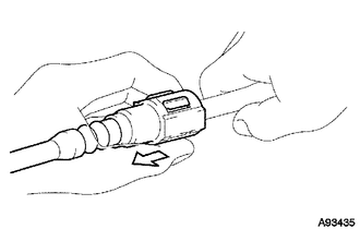
(g) Perform the following procedure when connecting a fuel tube connector (quick type B):
(1) Line up the two parts of the pipes to be connected, and fully push the fuel tube connector and pipe together until they are fully seated. Push the retainer into the connector until its claws lock. If the pipe is difficult to push into the connector, apply a small amount of clean engine oil to the tip of the pipe and reinsert it.
(2) After connecting, check that the pipe and connector are securely connected by pulling on them.
(3) Inspect for fuel leaks (See page ).
(h) Observe the following precautions when handling a nylon tube:
CAUTION:
- Do not twist the connection part of the nylon tube or the quick connector when connecting them.
- Do not bend or twist the nylon tube.
- Do not remove the EPDM protector on the outside of the nylon tube.
- Do not pinch or kink the nylon tubes to prevent fuel leakage.
4. FUEL INJECTOR
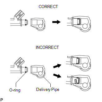
(a) Install the injector to the delivery pipe and the lower intake manifold as shown in the illustration.
 Text in Illustration
|
*1 |
Delivery Pipe |
|
*2 |
O-ring |
|
*3 |
Injector |
|
*4 |
Insulator |
NOTICE:
Before installing the injector, be sure to apply a light coat of gasoline or spindle oil where the delivery pipe contacts the injector O-ring.
(b) Observe the following precautions when removing and installing a fuel injector:
(1) Never reuse an O-ring.
(2) When placing a new O-ring onto an injector, do not damage the O-ring.
(3) Coat a new O-ring with spindle oil or gasoline before installing it.
NOTICE:
Do not use engine oil, gear oil or brake fluid.
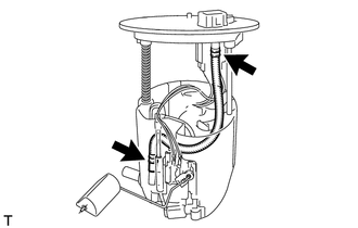
5. FUEL SUCTION TUBE ASSEMBLY WITH PUMP AND GAUGE
(a) Do not disconnect the tube shown in the illustration when disassembling the fuel suction tube assembly with pump and gauge. Doing so will cause reassembly of the fuel suction tube assembly with pump and gauge to be impossible as the tube is welded to the plate.
6. INSPECT FOR FUEL LEAK
(a) Check that there are no fuel leaks after doing maintenance on the fuel system
(See page ).
 Fuel System
...
 Parts Location
PARTS LOCATION
ILLUSTRATION
...
Other materials about Toyota Venza:
Adjustment
ADJUSTMENT
PROCEDURE
1. ADJUST STEERING WHEEL OFF CENTER
(a) Inspect steering wheel off center.
(1) Apply masking tape on the top center of the steering wheel and steering
column upper cover.
Text in Illustration
*1
...
Components
COMPONENTS
ILLUSTRATION
ILLUSTRATION
ILLUSTRATION
ILLUSTRATION
ILLUSTRATION
ILLUSTRATION
...
Inspection
INSPECTION
PROCEDURE
1. INSPECT UNLOCK WARNING SWITCH ASSEMBLY
(a) Measure the resistance according to the value(s) in the table below.
Standard Resistance:
Tester Connection
Condition
Specified Condition
...

0.133