Toyota Venza: Panel Switches do not Function
PROCEDURE
|
1. |
CHECK PANEL SWITCH |
(a) Check for foreign matter around the switches that might prevent operation.
OK:
No foreign matter is found.
| NG | .gif) |
REMOVE ANY FOREIGN MATTER FOUND |
|
.gif)
|
2. |
CHECK PANEL & STEERING SWITCH (OPERATION CHECK) |
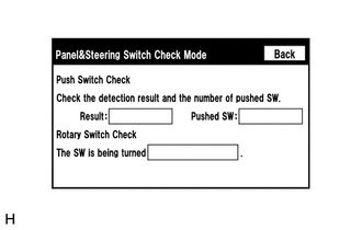
(a) Enter the "Panel & Steering Switch Check Mode" screen. Refer to Check Panel
& Steering Switch in Operation Check (See page .gif)
).
(b) Operate the abnormal switch and check if the switch status is correctly displayed.
OK:
The switch status is correctly displayed as operated.
| OK | |
REPLACE RADIO AND DISPLAY RECEIVER ASSEMBLY |
| NG | |
PROCEED TO NEXT SUSPECTED AREA SHOWN IN PROBLEM SYMPTOMS TABLE |
 Display does not Dim when Light Control Switch is Turned ON
PROCEDURE
1.
CHECK IMAGE QUALITY SETTING
(a) Turn the light control switch to the tail or head position.
(b) Check that the daytime screen setting on the display adj ...
 Touch Panel Switch does not Function
PROCEDURE
1.
CHECK MULTI-DISPLAY
(a) Check if there is any foreign matter caught between the display and exterior
frame of the multi-display.
OK:
No foreign matt ...
Other materials about Toyota Venza:
Removal
REMOVAL
PROCEDURE
1. REMOVE AUTOMATIC TRANSAXLE ASSEMBLY
HINT:
See the steps from "Remove Engine Assembly with transaxle" through "Remove Automatic
Transaxle Assembly" (See page ).
2. REMOVE AUTOMATIC TRANSAXLE OIL PAN SUB-ASSEMBLY
...
Electrical Key Oscillator(for Center Floor)
Components
COMPONENTS
ILLUSTRATION
Installation
INSTALLATION
PROCEDURE
1. INSTALL ELECTRICAL KEY OSCILLATOR
(a) Engage the clamp and install the electrical key oscillator.
NOTICE:
Be careful when installing the electrical key osci ...
Adjustment
ADJUSTMENT
PROCEDURE
1. PRECAUTIONS AND WORK DESCRIPTION
(a) The U660E automatic transaxle does not have an oil filler tube and oil level
gauge. When adding fluid, add fluid through the refill hole on the transaxle case.
The fluid level can be adjusted ...

0.1175