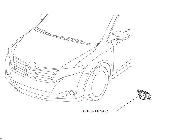
Toyota Venza: Outer Rear View Mirror Glass
Components
COMPONENTS
ILLUSTRATION
Inspection
INSPECTION
PROCEDURE
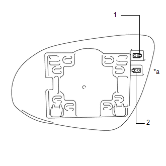
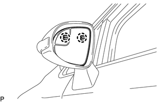
1. INSPECT OUTER MIRROR RH
|
(a) Check the outer mirror heater operation. (1) Measure the resistance according to the value(s) in the table below. Standard Resistance:
If the result is not as specified, replace the outer mirror RH. |
|
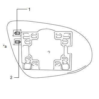
2. INSPECT OUTER MIRROR LH
|
(a) Check the outer mirror heater operation. (1) Measure the resistance according the value(s) in the table below. Standard Resistance:
If the result is not as specified, replace the outer mirror LH. |
|
Removal
REMOVAL
PROCEDURE
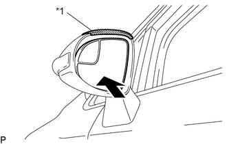
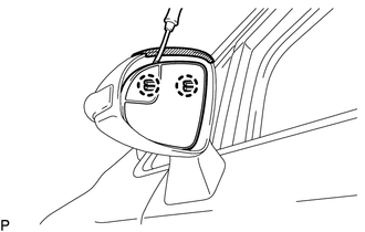
1. REMOVE OUTER MIRROR
|
(a) Push the lower part of the outer mirror surface and tilt it. Text in Illustration
|
|
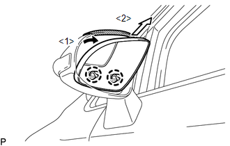
(b) Apply protective tape as shown in the illustration.
|
(c) Using a clip remover, disengage the 2 claws at the upper part of the outer mirror. |
|
|
(d) Disengage the 2 claws and disconnect the outer mirror as shown in the illustration. |
|
|
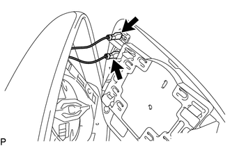
(e) Disconnect the 2 connectors and remove the outer mirror. |
|
Installation
INSTALLATION
PROCEDURE
1. INSTALL OUTER MIRROR
(a) Connect the 2 connectors.
|
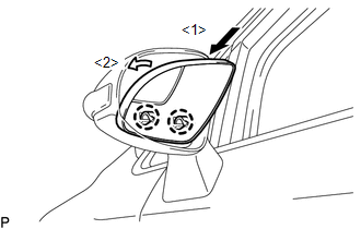
(b) Engage the 2 claws on the lower part of the outer mirror to the outer rear view mirror assembly as shown in the illustration. |
|
|
(c) Engage the 2 claws on the upper part of the outer mirror to the outer rear view mirror assembly. |
|
 Outer Rear View Mirror Cover
Components
COMPONENTS
ILLUSTRATION
Installation
INSTALLATION
PROCEDURE
1. INSTALL OUTER MIRROR COVER
(a) Engage the 7 claws to install the outer mirror cover.
...

Other materials about Toyota Venza:
ECU Power Source Circuit
DESCRIPTION
This is the power source for the tire pressure warning ECU.
WIRING DIAGRAM
CAUTION / NOTICE / HINT
NOTICE:
When replacing the tire pressure warning ECU, read the transmitter IDs
stored in the old ECU using the Techstream and writ ...
Cruise Control Switch Circuit
DESCRIPTION
The cruise control main switch operates 7 functions: SET, -, TAP-DOWN, RES, +,
TAP-UP, and CANCEL. The SET, TAP-DOWN, and - functions, and the RES, TAP-UP, and
+ functions are operated with the same switch. The cruise control main switch is
...
Inspection
INSPECTION
PROCEDURE
1. INSPECT INTEGRATION RELAY
(a) Inner circuit (for 2GR-FE)
(1) for EFI MAIN relay
Measure the resistance according to the value(s) in the table
below.
Standard Resistance:
...

0.1248