Toyota Venza: Outer Rear View Mirror Cover
Components
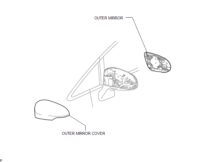
COMPONENTS
ILLUSTRATION
Installation
INSTALLATION
PROCEDURE
1. INSTALL OUTER MIRROR COVER
|
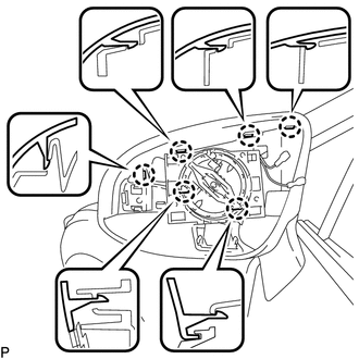
(a) Engage the 7 claws to install the outer mirror cover. |
|
2. INSTALL OUTER MIRROR
.gif)
Removal
REMOVAL
PROCEDURE
1. REMOVE OUTER MIRROR
.gif)
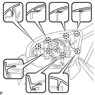
2. REMOVE OUTER MIRROR COVER
|
(a) Disengage the 6 claws. |
|
|
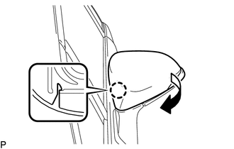
(b) Disengage the claw and remove the outer mirror cover as shown in the illustration. |
|
 Installation
INSTALLATION
PROCEDURE
1. INSTALL OUTER REAR VIEW MIRROR ASSEMBLY
(a) Engage the 3 claws to install the outer rear view mirror assembly
as shown in the illustration.
...
 Outer Rear View Mirror Glass
Components
COMPONENTS
ILLUSTRATION
Inspection
INSPECTION
PROCEDURE
1. INSPECT OUTER MIRROR RH
(a) Check the outer mirror heater operation.
(1) Measure the resistance accordi ...
Other materials about Toyota Venza:
Meter Illumination is Always Dark
DESCRIPTION
In this circuit, the meter CPU receives auto dimmer signals from the main body
ECU (driver side junction block assembly) using the CAN communication system (CAN
No. 1 Bus). When the meter CPU receives an auto dimmer signal, it dims the meter
...
TC and CG Terminal Circuit
DESCRIPTION
DTC output mode is set by connecting terminals 13 (TC) and 4 (CG) of the DLC3.
The DTCs are indicated by the blinking pattern of the tire pressure warning light.
WIRING DIAGRAM
HINT:
When various warning lights blink continuously, a ground ...
Disposal
DISPOSAL
PROCEDURE
1. DISPOSE OF FRONT SHOCK ABSORBER ASSEMBLY
(a) Position the front shock absorber assembly level with the piston
rod fully extended. Using a drill, make a hole in the cylinder between A
and B as shown in the illustratio ...

0.1238