Toyota Venza: BUS IC Communication Malfunction (B1497/97)
DESCRIPTION
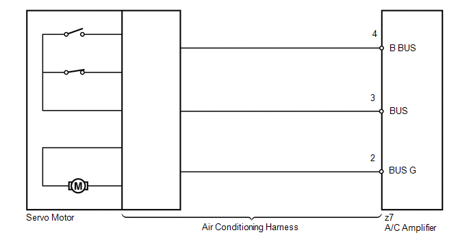
The air conditioning harness connects the A/C amplifier and each servo. The A/C amplifier supplies power and sends operation instructions to each servo through the air conditioning harness. Each servo sends the damper position information to the A/C amplifier.
|
DTC No. |
DTC Detection Condition |
Trouble Area |
|---|---|---|
|
B1497/97 |
Communication line error or open |
|
WIRING DIAGRAM
PROCEDURE
|
1. |
INSPECT A/C AMPLIFIER |
|
(a) Remove the A/C amplifier with the connectors still connected. |
|
(b) Measure the resistance according to the value(s) in the table below.
Standard Resistance:
|
Tester Connection |
Condition |
Specified Condition |
|---|---|---|
|
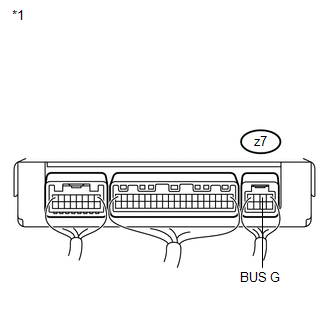
z7-2 (BUS G) - Body ground |
Always |
Below 1 Ω |
|
*1 |
Component with harness connected (A/C Amplifier) |
| NG | .gif) |
REPLACE A/C AMPLIFIER |
|
.gif)
|
2. |
INSPECT A/C AMPLIFIER |
|
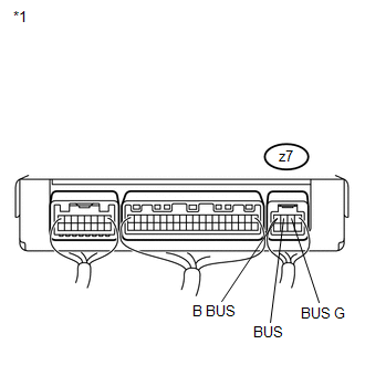
(a) Measure the voltage according to the value(s) in the table below. Standard Voltage:
|
|
| OK | |
REPLACE AIR CONDITIONING HARNESS |
| NG | |
REPLACE A/C AMPLIFIER |
 Compressor Solenoid Circuit (B1451/51)
DESCRIPTION
In this circuit, the A/C compressor receives a refrigerant compression demand
signal from the A/C amplifier.
Based on this signal, the A/C compressor changes the amount of compressor o ...
 Air Mix Damper Control Servo Motor Circuit (Driver Side) (B1446/46)
DESCRIPTION
The air mix control servo motor sends pulse signals to indicate the damper position
to the A/C amplifier. The A/C amplifier activates the motor (normal or reverse)
based on these sign ...
Other materials about Toyota Venza:
Fail-safe Chart
FAIL-SAFE CHART
1. HID Headlight System
(a) Light Control ECU
(1) The light control ECU stops illuminating the HID headlights when any of the
following abnormalities are detected.
Condition
Content
Open in output si ...
Driver Side Power Mirror cannot be Adjusted with Power Mirror Switch
SYSTEM DESCRIPTION
When the mirror adjust switch is operated, the main body ECU (driver side junction
block assembly) detects the switch operation and sends the mirror adjust switch
signal to the outer mirror control ECU assembly (driver door) via CAN com ...
Camshaft Position Sensor
Components
COMPONENTS
ILLUSTRATION
Installation
INSTALLATION
PROCEDURE
1. INSTALL CAMSHAFT POSITION SENSOR (for Exhaust Side)
(a) Apply a light coat of engine oil to the O-ring of the camshaft position sensor.
NOTICE:
If reusing the camshaft pos ...

0.1325