Toyota Venza: On-vehicle Inspection
ON-VEHICLE INSPECTION
PROCEDURE
1. INSPECT ENGINE COOLANT
See page .gif)
2. INSPECT ENGINE OIL
See page
3. INSPECT BATTERY
See page
4. INSPECT AIR CLEANER FILTER ELEMENT SUB-ASSEMBLY
(a) Remove the air cleaner filter element sub-assembly.
(b) Visually check that the air cleaner filter is not excessively damaged or oily. If necessary, replace the air cleaner filter.
HINT:
- If there is any dirt or a blockage in the air cleaner filter element sub-assembly, clean it with compressed air.
- If any dirt or a blockage remains even after cleaning the air cleaner filter element sub-assembly with compressed air, replace it.
(c) Install the air cleaner filter element sub-assembly.
5. INSPECT SPARK PLUG
See page
6. INSPECT VALVE LASH ADJUSTER ASSEMBLY NOISE
(a) Rev up the engine several times. Check that the engine does not emit unusual noises.
If unusual noises occur, warm up the engine and idle it for over 30 minutes. Then perform the inspection above again.
If any defects or problems are found during the inspection above, perform a lash
adjuster inspection (See page ).
7. INSPECT IGNITION TIMING
(a) Warm up and stop the engine.
(b) When using the Techstream:
(1) Connect the Techstream to the DLC3.
(2) Start the engine and idle it.
(3) Turn the Techstream main switch on.
(4) Enter the following menus: Powertrain / Engine / Data List / IGN Advance.
Standard ignition timing:
5 to 15° BTDC at idle
HINT:
Refer to the Techstream operator's manual for further details.
If the ignition timing is not as specified, check the valve timing.
(5) Check that the ignition timing advances immediately when the engine speed is increased.
(6) Enter the following menus: Powertrain / Engine / Active Test / Connect the TC and TE1 / ON.
(7) Monitor IGN Advance of the Data List.
Standard ignition timing:
8 to 12° BTDC at idle
HINT:
Refer to the Techstream operator's manual for further details.
If the ignition timing is not as specified, check the valve timing.
(8) Enter the following menus: Connect the TC and TE1 / OFF.
(9) Turn the ignition switch off.
(10) Disconnect the Techstream from the DLC3.
(c) When not using the Techstream:
(1) Remove the No. 1 engine cover sub-assembly.
|
(2) Connect the tester probe of a timing light to the wire of the ignition coil connector for the No. 1 cylinder. NOTICE: Use a timing light that detects primary signals. |
|
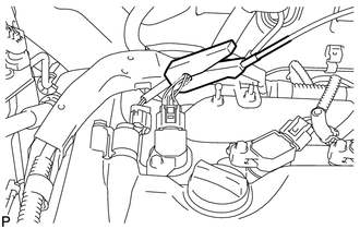
|
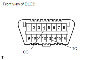
(3) Using SST, connect terminals 13 (TC) and 4 (CG) of the DLC3. SST: 09843-18040 NOTICE:
|
|
(4) Using a timing light, check the ignition timing.
Standard ignition timing:
8 to 12° BTDC at idle
(5) Remove SST from the DLC3.
(6) Check the ignition timing.
Standard ignition timing:
5 to 15° BTDC at idle
If the ignition timing is not as specified, check the valve timing.
(7) Check that the ignition timing advances immediately when the engine speed is increased.
(8) Disconnect the timing light from the engine.
(9) Install the No. 1 engine cover sub-assembly.
8. INSPECT ENGINE IDLE SPEED
(a) Warm up and stop the engine.
(b) When using the Techstream:
(1) Connect the Techstream to the DLC3.
NOTICE:
Switch off all accessories and the A/C before connecting the Techstream.
(2) Race the engine at 2500 rpm for approximately 90 seconds.
(3) Turn the Techstream on.
(4) Enter the following menus: Powertrain / Engine / Data List / Engine Speed.
Standard idle speed:
600 to 700 rpm
HINT:
Refer to the Techstream operator's manual for further details.
NOTICE:
When checking the idle speed, the transmission should be in neutral.
If the idle speed is not as specified, check the air intake system.
(5) Disconnect the Techstream from the DLC3.
(c) When not using the Techstream:
|
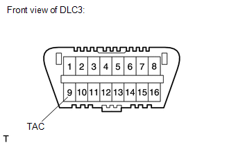
(1) Using SST, connect a tachometer probe to terminal 9 (TAC) of the DLC3. SST: 09843-18030 NOTICE: Confirm the terminal number before connecting the probe. Connecting the wrong terminals can damage the engine. |
|
(2) Race the engine at 2500 rpm for approximately 90 seconds.
(3) Check the idle speed.
Standard idle speed:
600 to 700 rpm
NOTICE:
- Turn all electrical systems and the A/C off.
- Inspect the idle speed with the cooling fans off.
- When checking the idle speed, the transaxle should be in neutral.
If the speed is not as specified, check the air intake system.
(4) Disconnect the tachometer probe from the DLC3.
9. INSPECT COMPRESSION
(a) Warm up and stop the engine.
(b) Check for DTCs (See page ).
(c) Remove the No. 1 engine cover sub-assembly.
(d) Disconnect the 4 fuel injector connectors.
(e) Remove the 4 bolts and 4 ignition coils.
(f) Remove the 4 spark plugs.
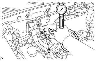
|
(g) Insert a compression gauge into the spark plug hole. |
|
(h) Fully open the throttle.
(i) While cranking the engine, measure the compression pressure.
Standard compression pressure:
1450 kPa (14.7 kgf/cm2, 210 psi) or higher
Minimum pressure:
980 kPa (9.9 kgf/cm2, 142 psi)
Difference between each cylinder:
200 kPa (2.0 kgf/cm2, 29 psi) or less
HINT:
Always use a fully charged battery to obtain an engine speed of 250 rpm or more.
(j) If the cylinder compression is low in one or more cylinders, pour a small amount of engine oil into the cylinder with low compression through its spark plug hole. Then inspect the cylinder compression pressure again.
HINT:
- If adding oil helps boost the compression, it is likely that the piston rings and/or cylinder bore is worn or damaged.
- If pressure stays low, a valve may be stuck or seated improperly, or there may be leakage in the gasket.
(k) Install the 4 spark plugs.
Torque:
25 N·m {254 kgf·cm, 18 ft·lbf}
(l) Install the 4 ignition coils with the 4 bolts.
Torque:
10 N·m {102 kgf·cm, 7 ft·lbf}
(m) Connect the 4 fuel injector connectors.
(n) Install the No. 1 engine cover sub-assembly.
(o) Clear the DTCs (See page ).
10. INSPECT CO/HC
HINT:
This check determines whether or not the idle CO/HC complies with regulations.
(a) Start the engine.
(b) Keep the engine speed at 2500 rpm for approximately 180 seconds.
(c) Insert the CO/HC meter testing probe at least 40 cm (1.31 ft.) into the tailpipe during idling.
(d) Immediately check CO/HC concentration at idle and 2500 rpm.
HINT:
- When performing the 2 mode (2500 rpm and idle) test, follow the measurement order prescribed by the applicable local regulations.
- If the CO/HC concentration does not comply with regulations, troubleshoot in the order given below.
(1) Check for DTCs (See page ).
(2) See the table below for possible causes, and then inspect and correct the applicable causes if necessary.
|
CO |
HC |
Symptom |
Causes |
|---|---|---|---|
|
Normal |
High |
Rough idle |
|
|
Low |
High |
Rough idle (Fluctuating HC reading) |
|
|
High |
High |
Rough idle (Black smoke from exhaust) |
|
 Engine
...
 Engine Assembly
...
Other materials about Toyota Venza:
On-vehicle Inspection
ON-VEHICLE INSPECTION
PROCEDURE
1. INSPECT BRAKE BOOSTER ASSEMBLY
(a) Airtightness check
(1) Start the engine and stop it after 1 or 2 minutes. Slowly depress
the brake pedal several times.
HINT:
If the pedal can be depressed to the ...
Back Door Closer does not Operate
DESCRIPTION
When the back door closer does not operate, one of the following may be the cause:
1) improper fit of the back door, or a foreign object is stuck in the back door
or 2) initialization of the power back door ECU (power back door motor unit)*1, ...
Reassembly
REASSEMBLY
PROCEDURE
1. INSTALL FRONT BUMPER SIDE RETAINER LH
(a) Engage the claw and install the front bumper side retainer LH.
Text in Illustration
*1
Bolt
*2
S ...

0.1486