Toyota Venza: On-vehicle Inspection
ON-VEHICLE INSPECTION
CAUTION / NOTICE / HINT
CAUTION:
Be sure to follow the correct removal and installation procedures of the front seat side airbag assembly.
PROCEDURE
1. INSPECT FRONT SEAT SIDE AIRBAG ASSEMBLY (VEHICLE NOT INVOLVED IN COLLISION)
(a) Perform a diagnostic system check (See page
.gif) ).
).
|
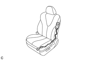
(b) Visually check for defects with the front seat side airbag assembly installed on the vehicle. (1) The defects are as follows:
OK: No defects are found. HINT: If any of the defects is found, replace the separate type front seatback pad or separate type front seatback cover with a new one. |
|
2. INSPECT FRONT SEAT SIDE AIRBAG ASSEMBLY (VEHICLE INVOLVED IN COLLISION AND AIRBAG HAS NOT DEPLOYED)
(a) Perform a diagnostic system check (See page
).
|
(b) Visually check for defects with the front seat side airbag assembly removed from the vehicle. (1) The defects are as follows:
OK: No defects are found. HINT: If any of the defects is found, replace the front seat side airbag assembly with a new one. |
|

 Components
COMPONENTS
ILLUSTRATION
...
 Removal
REMOVAL
PROCEDURE
1. PRECAUTION
CAUTION:
Be sure to read Precaution thoroughly before servicing (See page
).
If the front seat side airbag assembly was deployed, replace the front ...
Other materials about Toyota Venza:
Antenna location and effective range
- Antenna location
1. Antennas outside cabin
2. Antennas inside cabin
3. Antenna outside luggage compartment
- Effective range (areas within which the electronic key is detected)
When locking or unlocking the doors The system can be operat ...
Security Indicator Light Circuit
DESCRIPTION
The security indicator light blinks continuously due to a continuous signal received
from the certification ECU (smart key ECU assembly) while the engine immobiliser
is set.
WIRING DIAGRAM
CAUTION / NOTICE / HINT
NOTICE:
If the certifica ...
System Description
SYSTEM DESCRIPTION
1. ENGINE IMMOBILISER SYSTEM DESCRIPTION
The immobiliser system is a theft deterrent system that determines whether to
disable starting of the SFI system based on a comparison of the key ID code and
the vehicle pre-registered code. The ...

0.1447