Toyota Venza: Occupant Classification System Malfunction (B1650/32)
DESCRIPTION
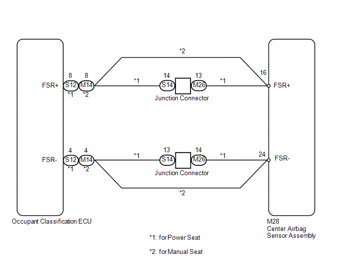
The occupant classification system circuit consists of the center airbag sensor assembly and occupant classification system.
If the center airbag sensor assembly receives signals from the occupant classification ECU, it determines whether the front passenger airbag and front seat belt pretensioner RH should be operated.
DTC B1650/32 is stored when a malfunction is detected in the occupant classification system circuit.
|
DTC No. |
DTC Detection Condition |
Trouble Area |
|---|---|---|
|
B1650/32 |
|
|
WIRING DIAGRAM
PROCEDURE
|
1. |
CHECK DTC (OCCUPANT CLASSIFICATION ECU) |
(a) Turn the ignition switch to ON.
(b) Using the Techstream, check for DTCs of the occupant classification ECU (See
page .gif) ).
).
OK:
DTC is not output.
| NG | .gif) |
REPAIR CIRCUITS INDICATED BY OUTPUT DTCS |
|
.gif)
|
2. |
CHECK CONNECTORS |
(a) Turn the ignition switch off.
(b) Disconnect the cable from the negative (-) battery terminal, and wait for at least 90 seconds.
(c) for Power seat:
Check that the connectors are properly connected to the center airbag sensor assembly and occupant classification ECU. Also check that the connectors that link the front seat wire RH, junction connector and No. 2 floor wire are properly connected.
(d) for Manual seat:
Check that the connectors are properly connected to the center airbag sensor assembly and occupant classification ECU.
OK:
The connectors are properly connected.
HINT:
If the connectors are not connected securely, reconnect the connectors and proceed to the next inspection.
(e) for Power seat:
Disconnect the connectors from the center airbag sensor assembly and occupant classification ECU. Also disconnect the connectors that link the front seat wire RH, junction connector and No. 2 floor wire.
(f) for Manual seat:
Disconnect the connectors from the center airbag sensor assembly and occupant classification ECU.
(g) Check that the connector terminals are not damaged.
OK:
The terminals are not deformed or damaged.
Result|
Result |
Proceed to |
|---|---|
|
OK |
A |
|
NG (for Power seat) |
B |
|
NG (for Manual seat) |
C |
| B | |
REPLACE WIRE HARNESS |
| C | |
REPLACE NO. 2 FLOOR WIRE |
|
|
3. |
CHECK VEHICLE CONDITION |
(a) Check the passenger seat type.
Result|
Result |
Proceed to |
|---|---|
|
for Manual seat |
A |
|
for Power seat |
B |
| B | |
GO TO STEP 8 |
|
|
4. |
CHECK NO. 2 FLOOR WIRE (OPEN) |
(a) Using SST, connect terminals 16 (FSR+) and 24 (FSR-) of connector B.
NOTICE:
Do not forcibly insert SST into the terminals of the connector when connecting.
SST: 09843-18040
(b) Measure the resistance according to the value(s) in the table below.
Standard Resistance:
|
Tester Connection |
Condition |
Specified Condition |
|---|---|---|
|
M14-8 (FSR+) - M14-4 (FSR-) |
Always |
Below 1 Ω |
|
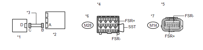
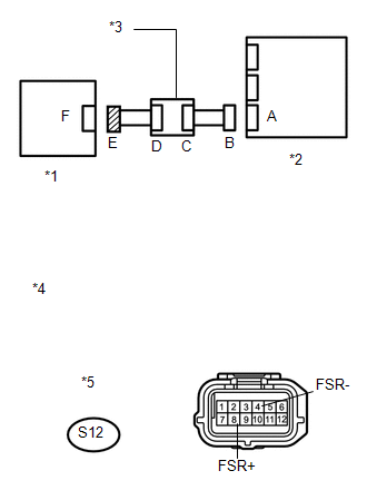
*1 |
Occupant Classification ECU |
*2 |
Center Airbag Sensor Assembly |
|
*3 |
No. 2 Floor Wire |
*4 |
Front view of wire harness connector (to Center Airbag Sensor Assembly) |
|
*5 |
Front view of wire harness connector (to Occupant Classification ECU) |
*6 |
Connector B |
|
*7 |
Connector C |
- |
- |
| NG | |
REPLACE NO. 2 FLOOR WIRE |
|
|
5. |
CHECK NO. 2 FLOOR WIRE (SHORT) |
|
(a) Disconnect SST from connector B. |
|
(b) Measure the resistance according to the value(s) in the table below.
Standard Resistance:
|
Tester Connection |
Condition |
Specified Condition |
|---|---|---|
|
M14-8 (FSR+) - M14-4 (FSR-) |
Always |
1 MΩ or higher |
|
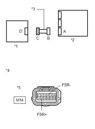
*1 |
Occupant Classification ECU |
|
*2 |
Center Airbag Sensor Assembly |
|
*3 |
No. 2 Floor Wire |
|
*4 |
Front view of wire harness connector (to Occupant Classification ECU) |
|
*5 |
Connector C |
| NG | |
REPLACE NO. 2 FLOOR WIRE |
|
|
6. |
CHECK NO. 2 FLOOR WIRE (SHORT TO B+) |
|
(a) Connect the cable to the negative (-) battery terminal. |
|
(b) Turn the ignition switch to ON.
(c) Measure the voltage according to the value (s) in the table below.
Standard Voltage:
|
Tester Connection |
Switch Condition |
Specified Condition |
|---|---|---|
|
M14-8 (FSR+) - Body ground |
Ignition switch ON |
Below 1 V |
|
M14-4 (FSR-) - Body ground |
Ignition switch ON |
Below 1 V |
|
*1 |
Occupant Classification ECU |
|
*2 |
Center Airbag Sensor Assembly |
|
*3 |
No. 2 Floor Wire |
|
*4 |
Front view of wire harness connector (to Occupant Classification ECU) |
|
*5 |
Connector C |
| NG | |
REPLACE NO. 2 FLOOR WIRE |
|
|
7. |
CHECK NO. 2 FLOOR WIRE (SHORT TO GROUND) |
|
(a) Turn the ignition switch off. |
|
(b) Disconnect the cable from the negative (-) battery terminal, and wait for at least 90 seconds.
(c) Measure the resistance according to the value(s) in the table below.
Standard Resistance:
|
Tester Connection |
Condition |
Specified Condition |
|---|---|---|
|
M14-8 (FSR+) - Body ground |
Always |
1 MΩ or higher |
|
M14-4 (FSR-) - Body ground |
Always |
1 MΩ or higher |
|
*1 |
Occupant Classification ECU |
|
*2 |
Center Airbag Sensor Assembly |
|
*3 |
No. 2 Floor Wire |
|
*4 |
Front view of wire harness connector (to Occupant Classification ECU) |
|
*5 |
Connector C |
HINT:
After replacing the center airbag sensor assembly, check for DTCs of the center
airbag sensor assembly. If DTC B1650/32 is detected, replace the occupant classification
ECU (See page ) and perform "zero point calibration"
and "sensitivity check" of the occupant classification system (See page
).
| OK | |
REPLACE CENTER AIRBAG SENSOR ASSEMBLY |
| NG | |
REPLACE NO. 2 FLOOR WIRE |
|
8. |
CHECK OCCUPANT CLASSIFICATION SYSTEM CIRCUIT (OPEN) |
(a) Connect the connectors that link the front seat wire RH, junction connector and No. 2 floor wire.
(b) Using SST, connect terminals 16 (FSR+) and 24 (FSR-) of connector B.
NOTICE:
Do not forcibly insert SST into the terminals of the connector when connecting.
SST: 09843-18040
(c) Measure the resistance according to the value(s) in the table below.
Standard Resistance:
|
Tester Connection |
Condition |
Specified Condition |
|---|---|---|
|
S12-8 (FSR+) - S12-4 (FSR-) |
Always |
Below 1 Ω |
|
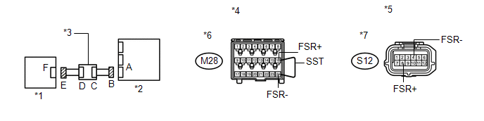
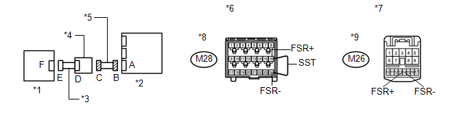
*1 |
Occupant Classification ECU |
*2 |
Center Airbag Sensor Assembly |
|
*3 |
Junction Connector |
*4 |
Front view of wire harness connector (to Center Airbag Sensor Assembly) |
|
*5 |
Front view of wire harness connector (to Occupant Classification ECU) |
*6 |
Connector B |
|
*7 |
Connector E |
- |
- |
| NG | |
GO TO STEP 12 |
|
|
9. |
CHECK OCCUPANT CLASSIFICATION SYSTEM CIRCUIT (SHORT) |
|
(a) Disconnect SST from connector B. |
|
(b) Measure the resistance according to the value(s) in the table below.
Standard Resistance:
|
Tester Connection |
Condition |
Specified Condition |
|---|---|---|
|
S12-8 (FSR+) - S12-4 (FSR-) |
Always |
1 MΩ or higher |
|
*1 |
Occupant Classification ECU |
|
*2 |
Center Airbag Sensor Assembly |
|
*3 |
Junction Connector |
|
*4 |
Front view of wire harness connector (to Occupant Classification ECU) |
|
*5 |
Connector E |
| NG | |
GO TO STEP 14 |
|
|
10. |
CHECK OCCUPANT CLASSIFICATION SYSTEM CIRCUIT (SHORT TO B+) |
|
(a) Connect the cable to the negative (-) battery terminal. |
|
(b) Turn the ignition switch to ON.
(c) Measure the voltage according to the value(s) in the table below.
Standard Voltage:
|
Tester Connection |
Switch Condition |
Specified Condition |
|---|---|---|
|
S12-8 (FSR+) - Body ground |
Ignition switch ON |
Below 1 V |
|
S12-4 (FSR-) - Body ground |
Ignition switch ON |
Below 1 V |
|
*1 |
Occupant Classification ECU |
|
*2 |
Center Airbag Sensor Assembly |
|
*3 |
Junction Connector |
|
*4 |
Front view of wire harness connector (to Occupant Classification ECU) |
|
*5 |
Connector E |
| NG | |
GO TO STEP 16 |
|
|
11. |
CHECK OCCUPANT CLASSIFICATION SYSTEM CIRCUIT (SHORT TO GROUND) |
|
(a) Turn the ignition switch off. |
|
(b) Disconnect the cable from the negative (-) battery terminal, and wait for at least 90 seconds.
(c) Measure the resistance according to the value(s) in the table below.
Standard Resistance:
|
Tester Connection |
Condition |
Specified Condition |
|---|---|---|
|
S12-8 (FSR+) - Body ground |
Always |
1 MΩ or higher |
|
S12-4 (FSR-) - Body ground |
Always |
1 MΩ or higher |
|
*1 |
Occupant Classification ECU |
|
*2 |
Center Airbag Sensor Assembly |
|
*3 |
Junction Connector |
|
*4 |
Front view of wire harness connector (to Occupant Classification ECU) |
|
*5 |
Connector E |
HINT:
After replacing the center airbag sensor assembly, check for DTCs of the center
airbag sensor assembly. If DTC B1650/32 is detected, replace the occupant classification
ECU (See page ) and perform "zero point calibration"
and "sensitivity check" of the occupant classification system (See page
).
| OK | |
REPLACE CENTER AIRBAG SENSOR ASSEMBLY |
| NG | |
GO TO STEP 18 |
|
12. |
CHECK NO. 2 FLOOR WIRE (OPEN) |
(a) Disconnect the junction connector from the No. 2 floor wire.
HINT:
SST already been inserted into connector B.
(b) Measure the resistance according to the value(s) in the table below.
Standard Resistance:
|
Tester Connection |
Condition |
Specified Condition |
|---|---|---|
|
M26-13 (FSR+) - M26-14 (FSR-) |
Always |
Below 1 Ω |
|
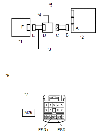
*1 |
Occupant Classification ECU |
*2 |
Center Airbag Sensor Assembly |
|
*3 |
Front Seat Wire RH |
*4 |
Junction Connector |
|
*5 |
No. 2 Floor Wire |
*6 |
Front view of wire harness connector (to Center Airbag Sensor Assembly) |
|
*7 |
Front view of wire harness connector (to Junction Connector) |
*8 |
Connector B |
|
*9 |
Connector C |
- |
- |
| NG | |
REPLACE NO. 2 FLOOR WIRE |
|
|
13. |
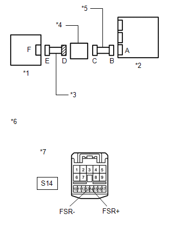
CHECK FRONT SEAT WIRE RH (OPEN) |
(a) Disconnect the front seat wire RH connector from the junction connector.
(b) Using SST, connect terminals 8 (FSR+) and 4 (FSR-) of connector E.
NOTICE:
Do not forcibly insert SST into the terminals of the connector when connecting the wire.
(c) Measure the resistance according to the value(s) in the table below.
Standard Resistance:
|
Tester Connection |
Condition |
Specified Condition |
|---|---|---|
|
S14-14 (FSR+) - S14-13 (FSR-) |
Always |
Below 1 Ω |
|
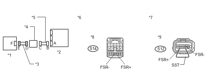
*1 |
Occupant Classification ECU |
*2 |
Center Airbag Sensor Assembly |
|
*3 |
Front Seat Wire RH |
*4 |
Junction Connector |
|
*5 |
No. 2 Floor Wire |
*6 |
Front view of wire harness connector (to Junction Connector) |
|
*7 |
Front view of wire harness connector (to Occupant Classification ECU) |
*8 |
Connector D |
|
*9 |
Connector E |
- |
- |
| OK | |
REPLACE JUNCTION CONNECTOR |
| NG | |
REPLACE FRONT SEAT WIRE RH |
|
14. |
CHECK NO. 2 FLOOR WIRE (SHORT) |
|
(a) Disconnect the junction connector from the No. 2 floor wire. |
|
(b) Measure the resistance according to the value(s) in the table below.
Standard Resistance:
|
Tester Connection |
Condition |
Specified Condition |
|---|---|---|
|
M26-13 (FSR+) - M26-14 (FSR-) |
Always |
1 MΩ or higher |
|
*1 |
Occupant Classification ECU |
|
*2 |
Center Airbag Sensor Assembly |
|
*3 |
Front Seat Wire RH |
|
*4 |
Junction Connector |
|
*5 |
No. 2 Floor Wire |
|
*6 |
Front view of wire harness connector (to Junction connector) |
|
*7 |
Connector C |
| NG | |
REPLACE NO. 2 FLOOR WIRE |
|
|
15. |
CHECK FRONT SEAT WIRE RH (SHORT) |
|
(a) Disconnect the front seat wire RH connector from the junction connector. |
|
(b) Measure the resistance according to the value(s) in the table below.
Standard Resistance:
|
Tester Connection |
Condition |
Specified Condition |
|---|---|---|
|
S14-14 (FSR+) - S14-13 (FSR-) |
Always |
1 MΩ or higher |
|
*1 |
Occupant Classification ECU |
|
*2 |
Center Airbag Sensor Assembly |
|
*3 |
Front Seat Wire RH |
|
*4 |
Junction Connector |
|
*5 |
No. 2 Floor Wire |
|
*6 |
Front view of wire harness connector (to Junction connector) |
|
*7 |
Connector D |
| OK | |
REPLACE JUNCTION CONNECTOR |
| NG | |
REPLACE FRONT SEAT WIRE RH |
|
16. |
CHECK NO. 2 FLOOR WIRE (SHORT TO B+) |
|
(a) Turn the ignition switch off. |
|
(b) Disconnect the cable from the negative (-) battery terminal, and wait for at least 90 seconds.
(c) Disconnect the junction connector from the No. 2 floor wire.
(d) Connect the cable to the negative (-) battery terminal.
(e) Turn the ignition switch to ON.
(f) Measure the voltage according to the value(s) in the table below.
Standard Voltage:
|
Tester Connection |
Switch Condition |
Specified Condition |
|---|---|---|
|
M26-13 (FSR+) - Body ground |
Ignition switch ON |
Below 1 V |
|
M26-14 (FSR-) - Body ground |
Ignition switch ON |
Below 1 V |
|
*1 |
Occupant Classification ECU |
|
*2 |
Center Airbag Sensor Assembly |
|
*3 |
Front Seat Wire RH |
|
*4 |
Junction Connector |
|
*5 |
No. 2 Floor Wire |
|
*6 |
Front view of wire harness connector (to Junction connector) |
|
*7 |
Connector C |
| NG | |
REPLACE NO. 2 FLOOR WIRE |
|
|
17. |
CHECK FRONT SEAT WIRE RH (SHORT TO B+) |
|
(a) Turn the ignition switch off. |
|
(b) Disconnect the cable from the negative (-) battery terminal, and wait for at least 90 seconds.
(c) Disconnect the front seat wire RH connector from the junction connector.
(d) Connect the cable to the negative (-) battery terminal.
(e) Turn the ignition switch to ON.
(f) Measure the voltage according to the value(s) in the table below.
Standard Voltage:
|
Tester Connection |
Switch Condition |
Specified Condition |
|---|---|---|
|
S14-14 (FSR+) - Body ground |
Ignition switch ON |
Below 1 V |
|
S14-13 (FSR-) - Body ground |
Ignition switch ON |
Below 1 V |
|
*1 |
Occupant Classification ECU |
|
*2 |
Center Airbag Sensor Assembly |
|
*3 |
Front Seat Wire RH |
|
*4 |
Junction Connector |
|
*5 |
No. 2 Floor Wire |
|
*6 |
Front view of wire harness connector (to Junction connector) |
|
*7 |
Connector D |
| OK | |
REPLACE JUNCTION CONNECTOR |
| NG | |
REPLACE FRONT SEAT WIRE RH |
|
18. |
CHECK NO. 2 FLOOR WIRE (SHORT TO GROUND) |
|
(a) Disconnect the junction connector from the No. 2 floor wire. |
|
(b) Measure the resistance according to the value(s) in the table below.
Standard Resistance:
|
Tester Connection |
Condition |
Specified Condition |
|---|---|---|
|
M26-13 (FSR+) - Body ground |
Always |
1 MΩ or higher |
|
M26-14 (FSR-) - Body ground |
Always |
1 MΩ or higher |
|
*1 |
Occupant Classification ECU |
|
*2 |
Center Airbag Sensor Assembly |
|
*3 |
Front Seat Wire RH |
|
*4 |
Junction Connector |
|
*5 |
No. 2 Floor Wire |
|
*6 |
Front view of wire harness connector (to Junction connector) |
|
*7 |
Connector C |
| NG | |
REPLACE NO. 2 FLOOR WIRE |
|
|
19. |
CHECK FRONT SEAT WIRE RH (SHORT TO GROUND) |
|
(a) Disconnect the front seat wire RH connector from the junction connector. |
|
(b) Measure the resistance according to the value(s) in the table below.
Standard Resistance:
|
Tester Connection |
Condition |
Specified Condition |
|---|---|---|
|
S14-14 (FSR+) - Body ground |
Always |
1 MΩ or higher |
|
S14-13 (FSR-) - Body ground |
Always |
1 MΩ or higher |
|
*1 |
Occupant Classification ECU |
|
*2 |
Center Airbag Sensor Assembly |
|
*3 |
Front Seat Wire RH |
|
*4 |
Junction Connector |
|
*5 |
No. 2 Floor Wire |
|
*6 |
Front view of wire harness connector (to Junction connector) |
|
*7 |
Connector D |
| OK | |
REPLACE JUNCTION CONNECTOR |
| NG | |
REPLACE FRONT SEAT WIRE RH |
 Seat Position Airbag Sensor Circuit Malfunction (B1653/35)
DESCRIPTION
The seat position airbag sensor circuit consists of the center airbag sensor
assembly and seat position airbag sensor.
DTC B1653/35 is stored when a malfunction is detected in the seat ...
 Lost Communication with Rear Airbag Sensor LH (B1637/82,B1638/82,B1647/82,B1697/82,B1698/82)
DESCRIPTION
The side collision sensor LH circuit (to determine deployment of the front seat
side airbag assembly LH and curtain shield airbag assembly LH) is composed of the
center airbag sensor ...
Other materials about Toyota Venza:
PS Warning Light Remains ON
DESCRIPTION
If the power steering ECU detects a malfunction, the P/S warning light comes
on. At this time, the power steering ECU stores a DTC in its memory.
WIRING DIAGRAM
1. w/ Smart Key System
2. w/o Smart Key System
CAUTION / NOTICE / HINT
NOTI ...
Inspection
INSPECTION
PROCEDURE
1. INSPECT FUEL PUMP ASSEMBLY WITH FILTER
(a) Inspect fuel pump resistance.
(1) Measure the resistance according to the value(s) in the table below.
Standard Resistance:
Tester Connection
Condition
...
Security Indicator Light Circuit
DESCRIPTION
Even when the theft deterrent system is in the disarmed state, the security indicator
blinks due to a signal output from the immobiliser system. The security indicator
blinks continuously due to a continuous signal received from the immobilise ...

0.155