Toyota Venza: Lost Communication with Rear Airbag Sensor LH (B1637/82,B1638/82,B1647/82,B1697/82,B1698/82)
DESCRIPTION
The side collision sensor LH circuit (to determine deployment of the front seat side airbag assembly LH and curtain shield airbag assembly LH) is composed of the center airbag sensor assembly, rear airbag sensor LH and side airbag sensor LH.
The rear airbag sensor LH and side airbag sensor LH detect impacts to the vehicle and send signals to the center airbag sensor assembly to determine if the airbag should be deployed.
These DTCs are stored when a malfunction is detected for the side collision sensor LH circuit (to determine deployment of the front seat side airbag assembly LH and curtain shield airbag assembly LH).
|
DTC No. |
DTC Detection Condition |
Trouble Area |
|---|---|---|
|
B1637/82 B1638/82 B1647/82 B1697/82 B1698/82 |
|
|
WIRING DIAGRAM
.png)
PROCEDURE
|
1. |
CHECK CURRENT DTC |
(a) Turn the ignition switch to ON, and wait for at least 60 seconds.
(b) Check for current DTCs (See page .gif) ).
).
|
Result |
Proceed to |
|---|---|
|
Current DTC B1638 is output. |
A |
|
Current DTC B1647 or 82 is output. |
B |
|
Current DTC B1697 or B1698 is output. |
C |
|
Current DTC B1637 is output. |
D |
|
Current DTC B1637, B1638, B1647, B1697, B1698 or 82 is not output. |
E |
HINT:
- DTCs indicating communication errors will be changed to DTCs indicating errors in initialization by turning the ignition switch off and then to ON again.
- Codes other than current DTCs B1637, B1638, B1647, B1697, B1698 and 82 may be output at this time, but they are not related to this check.
| B | .gif) |
GO TO STEP 3 |
| C | |
GO TO STEP 14 |
| D | |
GO TO STEP 21 |
| E | |
USE SIMULATION METHOD TO CHECK |
|
.gif)
|
2. |
CHECK HISTORY DTC |
(a) Turn the ignition switch to ON, and wait for at least 60 seconds.
(b) Check for history DTCs (See page ).
|
Result |
Proceed to |
|---|---|
|
History DTC B1637 is not output. |
A |
|
History DTC B1637 is output. |
B |
HINT:
Codes other than history DTC B1637 may be output at this time, but they are not related to this check.
| B | |
GO TO STEP 21 |
|
|
3. |
CHECK CONNECTORS |
(a) Turn the ignition switch off.
(b) Disconnect the cable from the negative (-) battery terminal, and wait for at least 90 seconds.
(c) Check that the connectors are properly connected to the center airbag sensor assembly, rear airbag sensor LH and side airbag sensor LH. Also check that the connectors that link the floor wire and front door wire LH are properly connected.
OK:
The connectors are properly connected.
HINT:
If the connectors are not connected securely, reconnect the connectors and proceed to the next inspection.
(d) Disconnect the connectors from the center airbag sensor assembly, rear airbag sensor LH and side airbag sensor LH. Also disconnect the connectors that link the floor wire and front door wire LH.
(e) Check that the terminals of connectors are not damaged.
OK:
The terminals are not deformed or damaged.
| NG | |
REPLACE WIRE HARNESS |
|
|
4. |
CHECK FLOOR WIRE (OPEN) |
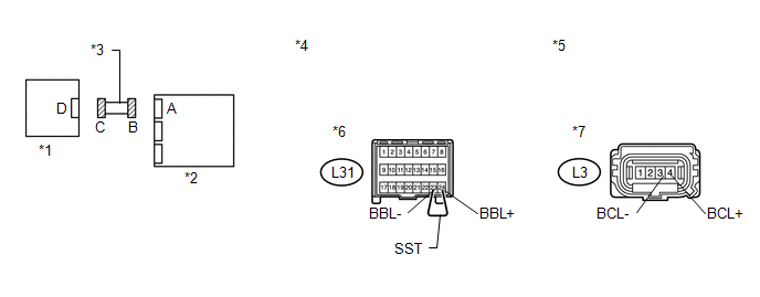
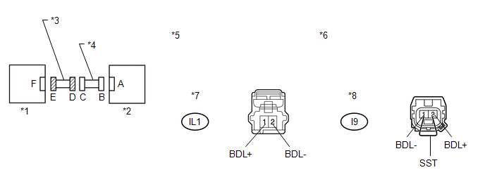
(a) Using SST, connect terminals 24 (BBL+) and 23 (BBL-) of connector B.
NOTICE:
Do not forcibly insert SST into the terminals of the connector when connecting.
SST: 09843-18040
(b) Measure the resistance according to the value(s) in the table below.
Standard Resistance:
|
Tester Connection |
Condition |
Specified Condition |
|---|---|---|
|
L3-4 (BCL+) - L3-3 (BCL-) |
Always |
Below 1 Ω |
|
*1 |
Rear Airbag Sensor LH |
*2 |
Center Airbag Sensor Assembly |
|
*3 |
Floor Wire |
*4 |
Front view of wire harness connector (to Center Airbag Sensor Assembly) |
|
*5 |
Front view of wire harness connector (to Rear Airbag Sensor LH) |
*6 |
Connector B |
|
*7 |
Connector C |
- |
- |
| NG | |
REPLACE FLOOR WIRE |
|
|
5. |
CHECK FLOOR WIRE (SHORT) |
|
(a) Disconnect SST from connector B. |
|
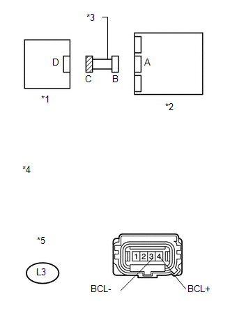
(b) Measure the resistance according to the value(s) in the table below.
Standard Resistance:
|
Tester Connection |
Condition |
Specified Condition |
|---|---|---|
|
L3-4 (BCL+) - L3-3 (BCL-) |
Always |
1 MΩ or higher |
|
*1 |
Rear Airbag Sensor LH |
|
*2 |
Center Airbag Sensor Assembly |
|
*3 |
Floor Wire |
|
*4 |
Front view of wire harness connector (to Rear Airbag Sensor LH) |
|
*5 |
Connector C |
| NG | |
REPLACE FLOOR WIRE |
|
|
6. |
CHECK FLOOR WIRE (SHORT TO B+) |
|
(a) Connect the cable to the negative (-) battery terminal. |
|
(b) Turn the ignition switch to ON.
(c) Measure the voltage according to the value(s) in the table below.
Standard Voltage:
|
Tester Connection |
Switch Condition |
Specified Condition |
|---|---|---|
|
L3-4 (BCL+) - Body ground |
Ignition switch ON |
Below 1 V |
|
L3-3 (BCL-) - Body ground |
Ignition switch ON |
Below 1 V |
|
*1 |
Rear Airbag Sensor LH |
|
*2 |
Center Airbag Sensor Assembly |
|
*3 |
Floor Wire |
|
*4 |
Front view of wire harness connector (to Rear Airbag Sensor LH) |
|
*5 |
Connector C |
| NG | |
REPLACE FLOOR WIRE |
|
|
7. |
CHECK FLOOR WIRE (SHORT TO GROUND) |
|
(a) Turn the ignition switch off. |
|
(b) Disconnect the cable from the negative (-) battery terminal, and wait for at least 90 seconds.
(c) Measure the resistance according to the value(s) in the table below.
Standard Resistance:
|
Tester Connection |
Condition |
Specified Condition |
|---|---|---|
|
L3-4 (BCL+) - Body ground |
Always |
1 MΩ or higher |
|
L3-3 (BCL-) - Body ground |
Always |
1 MΩ or higher |
|
*1 |
Rear Airbag Sensor LH |
|
*2 |
Center Airbag Sensor Assembly |
|
*3 |
Floor Wire |
|
*4 |
Front view of wire harness connector (to Rear Airbag Sensor LH) |
|
*5 |
Connector C |
| NG | |
REPLACE FLOOR WIRE |
|
|
8. |
CHECK WIRE HARNESS (OPEN) |
(a) Connect the connectors that link the floor wire and front door wire LH.
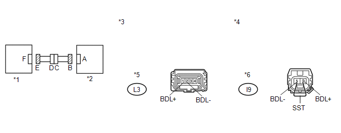
(b) Using SST, connect terminals 2 (BDL+) and 1 (BDL-) of connector E.
NOTICE:
Do not forcibly insert SST into the terminals of the connector when connecting.
SST: 09843-18040
(c) Measure the resistance according to the value(s) in the table below.
Standard Resistance:
|
Tester Connection |
Condition |
Specified Condition |
|---|---|---|
|
L3-1 (BDL+) - L3-2 (BDL-) |
Always |
Below 1 Ω |
|
*1 |
Side Airbag Sensor LH |
*2 |
Rear Airbag Sensor LH |
|
*3 |
Front view of wire harness connector (to Rear Airbag Sensor LH) |
*4 |
Front view of wire harness connector (to Side Airbag Sensor LH) |
|
*5 |
Connector B |
*6 |
Connector E |
| NG | |
GO TO STEP 22 |
|
|
9. |
CHECK WIRE HARNESS (SHORT) |
|
(a) Disconnect SST from connector E. |
|
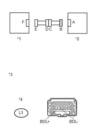
(b) Measure the resistance according to the value(s) in the table below.
Standard Resistance:
|
Tester Connection |
Condition |
Specified Condition |
|---|---|---|
|
L3-1 (BDL+) - L3-2 (BDL-) |
Always |
1 MΩ or higher |
|
*1 |
Side Airbag Sensor LH |
|
*2 |
Rear Airbag Sensor LH |
|
*3 |
Front view of wire harness connector (to Rear Airbag Sensor LH) |
|
*4 |
Connector B |
| NG | |
GO TO STEP 23 |
|
|
10. |
CHECK WIRE HARNESS (SHORT TO B+) |
|
(a) Connect the cable to the negative (-) battery terminal. |
|
(b) Turn the ignition switch to ON.
(c) Measure the voltage according to the value(s) in the table below.
Standard Voltage:
|
Tester Connection |
Switch Condition |
Specified Condition |
|---|---|---|
|
L3-1 (BDL+) - Body ground |
Ignition switch ON |
Below 1 V |
|
L3-2 (BDL-) - Body ground |
Ignition switch ON |
Below 1 V |
|
*1 |
Side Airbag Sensor LH |
|
*2 |
Rear Airbag Sensor LH |
|
*3 |
Front view of wire harness connector (to Rear Airbag Sensor LH) |
|
*4 |
Connector B |
| NG | |
GO TO STEP 24 |
|
|
11. |
CHECK WIRE HARNESS (SHORT TO GROUND) |
|
(a) Turn the ignition switch off. |
|
(b) Disconnect the cable from the negative (-) battery terminal, and wait for at least 90 seconds.
(c) Measure the resistance according to the value(s) in the table below.
Standard Resistance:
|
Tester Connection |
Condition |
Specified Condition |
|---|---|---|
|
L3-1 (BDL+) - Body ground |
Always |
1 MΩ or higher |
|
L3-2 (BDL-) - Body ground |
Always |
1 MΩ or higher |
|
*1 |
Side Airbag Sensor LH |
|
*2 |
Rear Airbag Sensor LH |
|
*3 |
Front view of wire harness connector (to Rear Airbag Sensor LH) |
|
*4 |
Connector B |
| NG | |
GO TO STEP 25 |
|
|
12. |
CHECK REAR AIRBAG SENSOR LH |
|
(a) Turn the ignition switch off. |
|
.png)
(b) Disconnect the cable from the negative (-) battery terminal, and wait for at least 90 seconds.
(c) Interchange the rear airbag sensor RH with LH and connect the connectors to them.
(d) Connect the cable to the negative (-) battery terminal.
(e) Turn the ignition switch to ON, and wait for at least 60 seconds.
(f) Clear the DTCs stored in memory (See page
).
(g) Turn the ignition switch off.
(h) Turn the ignition switch to ON, and wait for at least 60 seconds.
(i) Check for DTCs (See page ).
|
Result |
Proceed to |
|---|---|
|
DTC B1638, B1647 or 82 is output. |
A |
|
DTC B1633, B1642 or 81 is output. |
B |
|
DTCs B1633, B1642 or 81 and B1638, B1647 or 82 are not output. |
C |
|
*1 |
Rear Airbag Sensor RH |
|
*2 |
Center Airbag Sensor Assembly |
HINT:
Codes other than DTCs B1633, B1642 or 81 and B1638, B1647 or 82 may be output at this time, but they are not related to this check.
| B | |
REPLACE REAR AIRBAG SENSOR LH |
| C | |
USE SIMULATION METHOD TO CHECK |
|
|
13. |
CHECK SIDE AIRBAG SENSOR LH |
|
(a) Turn the ignition switch off. |
|
.png)
(b) Disconnect the cable from the negative (-) battery terminal, and wait for at least 90 seconds.
(c) Return the rear airbag sensor RH and LH to their original positions and connect the connectors.
(d) Interchange the side airbag sensor RH with LH and connect the connectors.
(e) Connect the cable to the negative (-) battery terminal.
(f) Turn the ignition switch to ON, and wait for at least 60 seconds.
(g) Clear the DTCs stored in memory (See page
).
(h) Turn the ignition switch off.
(i) Turn the ignition switch to ON, and wait for at least 60 seconds.
(j) Check for DTCs (See page ).
|
Result |
Proceed to |
|---|---|
|
DTCs B1633, B1642 or 81 and B1638, B1647 or 82 are not output. |
A |
|
DTC B1633, B1642 or 81 is output. |
B |
|
DTC B1638, B1647 or 82 is output. |
C |
|
*1 |
Side Airbag Sensor RH |
|
*2 |
Rear Airbag Sensor LH |
HINT:
Codes other than DTCs B1633, B1642 or 81 and B1638, B1647 or 82 may be output at this time, but they are not related to this check.
| A | |
USE SIMULATION METHOD TO CHECK |
| B | |
REPLACE SIDE AIRBAG SENSOR LH |
| C | |
REPLACE CENTER AIRBAG SENSOR ASSEMBLY |
|
14. |
CHECK CONNECTORS |
(a) Turn the ignition switch off.
(b) Disconnect the cable from the negative (-) battery terminal, and wait for at least 90 seconds.
(c) Check that the connectors are properly connected to the rear airbag sensor LH and side airbag sensor LH. Also check that the connectors that link the floor wire and front door wire LH are properly connected.
OK:
The connectors are properly connected.
HINT:
If the connectors are not connected securely, reconnect the connectors and proceed to the next inspection.
(d) Disconnect the connectors from the rear airbag sensor LH and side airbag sensor LH. Also disconnect the connectors that link the floor wire and front door wire LH.
(e) Check that the terminals of connectors are not damaged.
OK:
The terminals are not deformed or damaged.
| NG | |
REPLACE WIRE HARNESS |
|
|
15. |
CHECK WIRE HARNESS (OPEN) |
(a) Connect the connectors that link the floor wire and front door wire LH.
(b) Using SST, connect terminals 2 (BDL+) and 1 (BDL-) of connector E.
NOTICE:
Do not forcibly insert SST into the terminals of the connector when connecting.
SST: 09843-18040
(c) Measure the resistance according to the value(s) in the table below.
Standard Resistance:
|
Tester Connection |
Condition |
Specified Condition |
|---|---|---|
|
L3-1 (BDL+) - L3-2 (BDL-) |
Always |
Below 1 Ω |
|
*1 |
Side Airbag Sensor LH |
*2 |
Rear Airbag Sensor LH |
|
*3 |
Front view of wire harness connector (to Rear Airbag Sensor LH) |
*4 |
Front view of wire harness connector (to Side Airbag Sensor LH) |
|
*5 |
Connector B |
*6 |
Connector E |
| NG | |
GO TO STEP 22 |
|
|
16. |
CHECK WIRE HARNESS (SHORT) |
|
(a) Disconnect SST from connector E. |
|
(b) Measure the resistance according to the value(s) in the table below.
Standard Resistance:
|
Tester Connection |
Condition |
Specified Condition |
|---|---|---|
|
L3-1 (BDL+) - L3-2 (BDL-) |
Always |
1 MΩ or higher |
|
*1 |
Side Airbag Sensor LH |
|
*2 |
Rear Airbag Sensor LH |
|
*3 |
Front view of wire harness connector (to Rear Airbag Sensor LH) |
|
*4 |
Connector B |
| NG | |
GO TO STEP 23 |
|
|
17. |
CHECK WIRE HARNESS (SHORT TO B+) |
|
(a) Connect the cable to the negative (-) battery terminal. |
|
(b) Turn the ignition switch to ON.
(c) Measure the voltage according to the value(s) in the table below.
Standard Voltage:
|
Tester Connection |
Switch Condition |
Specified Condition |
|---|---|---|
|
L3-1 (BDL+) - Body ground |
Ignition switch ON |
Below 1 V |
|
L3-2 (BDL-) - Body ground |
Ignition switch ON |
Below 1 V |
|
*1 |
Side Airbag Sensor LH |
|
*2 |
Rear Airbag Sensor LH |
|
*3 |
Front view of wire harness connector (to Rear Airbag Sensor LH) |
|
*4 |
Connector B |
| NG | |
GO TO STEP 24 |
|
|
18. |
CHECK WIRE HARNESS (SHORT TO GROUND) |
|
(a) Turn the ignition switch off. |
|
(b) Disconnect the cable from the negative (-) battery terminal, and wait for at least 90 seconds.
(c) Measure the resistance according to the value(s) in the table below.
Standard Resistance:
|
Tester Connection |
Condition |
Specified Condition |
|---|---|---|
|
L3-1 (BDL+) - Body ground |
Always |
1 MΩ or higher |
|
L3-2 (BDL-) - Body ground |
Always |
1 MΩ or higher |
|
*1 |
Side Airbag Sensor LH |
|
*2 |
Rear Airbag Sensor LH |
|
*3 |
Front view of wire harness connector (to Rear Airbag Sensor LH) |
|
*4 |
Connector B |
| NG | |
GO TO STEP 25 |
|
|
19. |
CHECK SIDE AIRBAG SENSOR LH |
|
(a) Connect the connectors to the rear airbag sensor LH. |
|
(b) Interchange the side airbag sensor RH with LH and connect the connectors.
(c) Connect the cable to the negative (-) battery terminal.
(d) Turn the ignition switch to ON, and wait for at least 60 seconds.
(e) Clear the DTCs stored in memory (See page
).
(f) Turn the ignition switch off.
(g) Turn the ignition switch to ON, and wait for at least 60 seconds.
(h) Check for DTCs (See page ).
|
Result |
Proceed to |
|---|---|
|
DTC B1697 or B1698 is output. |
A |
|
DTC B1692 or B1693 is output. |
B |
|
DTCs B1692, B1693, B1697 and B1698 are not output. |
C |
|
*1 |
Side Airbag Sensor RH |
|
*2 |
Rear Airbag Sensor LH |
HINT:
Codes other than DTCs B1692, B1693, B1697 and B1698 may be output at this time, but they are not related to this check.
| B | |
REPLACE SIDE AIRBAG SENSOR LH |
| C | |
USE SIMULATION METHOD TO CHECK |
|
|
20. |
CHECK REAR AIRBAG SENSOR LH |
|
(a) Turn the ignition switch off. |
|
(b) Disconnect the cable from the negative (-) battery terminal, and wait for at least 90 seconds.
(c) Return the side airbag sensor RH and LH to their original positions and connect the connectors.
(d) Interchange the rear airbag sensor RH with LH and connect the connectors to them.
(e) Connect the cable to the negative (-) battery terminal.
(f) Turn the ignition switch to ON, and wait for at least 60 seconds.
(g) Clear the DTCs stored in memory (See page
).
(h) Turn the ignition switch off.
(i) Turn the ignition switch to ON, and wait for at least 60 seconds.
(j) Check for DTCs (See page ).
|
Result |
Proceed to |
|---|---|
|
DTCs B1692, B1693, B1697 and B1698 are not output. |
A |
|
DTC B1692 or B1693 is output. |
B |
|
DTC B1697 or B1698 is output. |
C |
|
*1 |
Rear Airbag Sensor RH |
|
*2 |
Center Airbag Sensor Assembly |
HINT:
Codes other than DTCs B1692, B1693, B1697 and B1698 may be output at this time, but they are not related to this check.
| A | |
USE SIMULATION METHOD TO CHECK |
| B | |
REPLACE REAR AIRBAG SENSOR LH |
| C | |
REPLACE CENTER AIRBAG SENSOR ASSEMBLY |
|
21. |
CHECK REAR AIRBAG SENSOR LH |
|
(a) Turn the ignition switch off. |
|
(b) Disconnect the cable from the negative (-) battery terminal, and wait for at least 90 seconds.
(c) Interchange the rear airbag sensor RH with LH and connect the connectors to them.
(d) Connect the cable to the negative (-) battery terminal.
(e) Turn the ignition switch to ON, and wait for at least 60 seconds.
(f) Clear the DTCs stored in memory (See page
).
(g) Turn the ignition switch off.
(h) Turn the ignition switch to ON, and wait for at least 60 seconds.
(i) Check for DTCs (See page ).
|
Result |
Proceed to |
|---|---|
|
DTCs B1632 and B1637 are not output. |
A |
|
DTC B1632 is output. |
B |
|
DTC B1637 is output. |
C |
|
*1 |
Rear Airbag Sensor RH |
|
*2 |
Center Airbag Sensor Assembly |
HINT:
Codes other than DTCs B1632 and B1637 may be output at this time, but they are not related to this check.
| A | |
USE SIMULATION METHOD TO CHECK |
| B | |
REPLACE REAR AIRBAG SENSOR LH |
| C | |
REPLACE CENTER AIRBAG SENSOR ASSEMBLY |
|
22. |
CHECK FRONT DOOR WIRE LH (OPEN) |
(a) Disconnect the front door wire LH connector from the floor wire.
HINT:
SST has already been inserted into connector E.
(b) Measure the resistance according to the value(s) in the table below.
Standard Resistance:
|
Tester Connection |
Condition |
Specified Condition |
|---|---|---|
|
IL1-1 (BDL+) - IL1-2 (BDL-) |
Always |
Below 1 Ω |
|
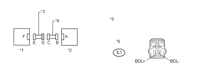
*1 |
Side Airbag Sensor LH |
*2 |
Rear Airbag Sensor LH |
|
*3 |
Front Door Wire LH |
*4 |
Floor Wire |
|
*5 |
Front view of wire harness connector (to Floor Wire) |
*6 |
Front view of wire harness connector (to Side Airbag Sensor LH) |
|
*7 |
Connector D |
*8 |
Connector E |
| OK | |
REPLACE FLOOR WIRE |
| NG | |
REPLACE FRONT DOOR WIRE LH |
|
23. |
CHECK FRONT DOOR WIRE LH (SHORT) |
(a) Disconnect the front door wire LH connector from the floor wire.
(b) Measure the resistance according to the value(s) in the table below.
Standard Resistance:
|
Tester Connection |
Condition |
Specified Condition |
|---|---|---|
|
IL1-1 (BDL+) - IL1-2 (BDL-) |
Always |
1 MΩ or higher |
|
*1 |
Side Airbag Sensor LH |
*2 |
Rear Airbag Sensor LH |
|
*3 |
Front Door Wire LH |
*4 |
Floor Wire |
|
*5 |
Front view of wire harness connector (to Floor Wire) |
*6 |
Connector D |
| OK | |
REPLACE FLOOR WIRE |
| NG | |
REPLACE FRONT DOOR WIRE LH |
|
24. |
CHECK FRONT DOOR WIRE LH (SHORT TO B+) |
(a) Turn the ignition switch off.
(b) Disconnect the cable from the negative (-) battery terminal, and wait for at least 90 seconds.
(c) Disconnect the front door wire LH connector from the floor wire.
(d) Connect the cable to the negative (-) battery terminal.
(e) Turn the ignition switch to ON.
(f) Measure the voltage according to the value(s) in the table below.
Standard Voltage:
|
Tester Connection |
Switch Condition |
Specified Condition |
|---|---|---|
|
IL1-1 (BDL+) - Body ground |
Ignition switch ON |
Below 1 V |
|
IL1-2 (BDL-) - Body ground |
Ignition switch ON |
Below 1 V |
|
*1 |
Side Airbag Sensor LH |
*2 |
Rear Airbag Sensor LH |
|
*3 |
Front Door Wire LH |
*4 |
Floor Wire |
|
*5 |
Front view of wire harness connector (to Floor Wire) |
*6 |
Connector D |
| OK | |
REPLACE FLOOR WIRE |
| NG | |
REPLACE FRONT DOOR WIRE LH |
|
25. |
CHECK FRONT DOOR WIRE LH (SHORT TO GROUND) |
(a) Disconnect the front door wire LH connector from the floor wire.
(b) Measure the resistance according to the value(s) in the table below.
Standard Resistance:
|
Tester Connection |
Condition |
Specified Condition |
|---|---|---|
|
IL1-1 (BDL+) - Body ground |
Always |
1 MΩ or higher |
|
IL1-2 (BDL-) - Body ground |
Always |
1 MΩ or higher |
|
*1 |
Side Airbag Sensor LH |
*2 |
Rear Airbag Sensor LH |
|
*3 |
Front Door Wire LH |
*4 |
Floor Wire |
|
*5 |
Front view of wire harness connector (to Floor Wire) |
*6 |
Connector D |
| OK | |
REPLACE FLOOR WIRE |
| NG | |
REPLACE FRONT DOOR WIRE LH |
 Occupant Classification System Malfunction (B1650/32)
DESCRIPTION
The occupant classification system circuit consists of the center airbag sensor
assembly and occupant classification system.
If the center airbag sensor assembly receives signals from ...
 Rear Airbag Sensor LH Circuit Malfunction (B1635/24)
DESCRIPTION
The side collision sensor LH circuit (to determine deployment of the front seat
side airbag assembly LH and curtain shield airbag assembly LH) is composed of the
center airbag sensor ...
Other materials about Toyota Venza:
Pressure Control Solenoid "C" Performance (Shift Solenoid Valve SL3) (P0796)
SYSTEM DESCRIPTION
The TCM uses the vehicle speed signal and signals from the transmission speed
sensors (NC, NT) to detect the actual gear (1st, 2nd, 3rd, 4th, 5th or 6th gear).
Then the TCM compares the actual gear with the shift schedule in the TCM memo ...
Navigation Voice Circuit
DESCRIPTION
This circuit is used when the voice switch of the steering pad switch assembly
is pushed.
Using this circuit, the navigation receiver assembly sends signals to the stereo
component amplifier assembly.
WIRING DIAGRAM
PROCEDURE
...
Back Door Lock
Components
COMPONENTS
ILLUSTRATION
Removal
REMOVAL
PROCEDURE
1. REMOVE BACK DOOR PANEL TRIM ASSEMBLY
2. REMOVE BACK DOOR LOCK ASSEMBLY
(a) Disconnect the connector.
(b) Disengage the c ...

0.15