Toyota Venza: No Answer-Back
DESCRIPTION
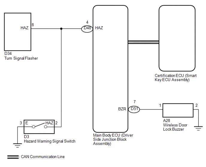
In some cases, wireless door lock control functions are normal but the hazard warning light and/or wireless door lock buzzer answer-back function(s) does not operate. In such cases, the main body ECU (driver side junction block assembly) hazard warning light and wireless door lock buzzer signal outputs may be malfunctioning.
WIRING DIAGRAM
CAUTION / NOTICE / HINT
NOTICE:
Troubleshooting should be started after confirming that the customize status of the answer-back function has been switched on.
PROCEDURE
|
1. |
READ VALUE USING TECHSTREAM (DOOR LOCK POSITION SWITCH) |
(a) Connect the Techstream to the DLC3.
(b) Turn the engine switch on (IG).
(c) Turn the Techstream on.
(d) Enter the following menus: Body Electrical / Main Body / Data List.
(e) Read the Data List according to the display on the Techstream.
Main Body (Main Body ECU (Driver Side junction Block Assembly))|
Tester Display |
Measurement Item/Range |
Normal Condition |
Diagnostic Note |
|---|---|---|---|
|
D-Door Lock Pos SW |
Driver door lock position switch signal/LOCK or UNLOCK |
ON: Driver side door is unlocked OFF: Driver side door is locked |
- |
|
P-Door Lock Pos SW |
Front passenger side door lock position switch signal/ON or OFF |
ON: Front passenger side door is unlocked OFF: Front passenger side door is locked |
- |
|
RR-Door Lock Pos SW |
Rear right side door lock position switch signal/ON or OFF |
ON: Rear right side door unlocked OFF: Rear right side door locked |
- |
|
RL-Door Lock Pos SW |
Rear left side door lock position switch signal/ON or OFF |
ON: Rear left side door unlocked OFF: Rear left side door locked |
- |
OK:
On the Techstream screen, the display changes between ON and OFF as shown in the chart above.
|
Result |
Proceed to |
|---|---|
|
OK |
A |
|
NG (for Driver Side) |
B |
|
NG (for Front Passenger Side) |
C |
|
NG (for Rear LH Side) |
D |
|
NG (for Rear RH Side) |
E |
| B | .gif) |
GO TO LIGHTING SYSTEM (Proceed to Door Unlock Detection Switch Circuit) |
| C | |
GO TO LIGHTING SYSTEM (Proceed to Door Unlock Detection Switch Circuit) |
| D | |
GO TO LIGHTING SYSTEM (Proceed to Door Unlock Detection Switch Circuit) |
| E | |
GO TO LIGHTING SYSTEM (Proceed to Door Unlock Detection Switch Circuit) |
|
.gif)
|
2. |
CHECK WIRELESS DOOR LOCK CONTROL FUNCTION |
(a) Check the wireless door lock control functions by operating the transmitter switches.
|
Result |
Proceed to |
|---|---|
|
Wireless door lock functions are normal but hazard warning light answer-back does not occur. |
A |
|
Wireless door lock functions are normal but wireless door lock buzzer answer-back does not occur. |
B |
|
Doors cannot be locked or unlocked with transmitter. |
C |
| B | |
GO TO STEP 6 |
| C | |
GO TO PROBLEM SYMPTOMS TABLE |
|
|
3. |
CHECK HAZARD WARNING LIGHT |
(a) Check that the hazard warning lights flash continuously when the hazard warning signal switch is pressed.
OK:
Hazard warning lights flash continuously.
| NG | |
GO TO LIGHTING SYSTEM |
|
|
4. |
PERFORM ACTIVE TEST USING TECHSTREAM (TURN SIGNAL FLASHER) |
(a) Connect the Techstream to the DLC3.
(b) Turn the engine switch on (IG).
(c) Enter the following menus: Body Electrical / Main Body / Active Test.
(d) Perform the Active Test according to the display on the Techstream.
Main Body (Main Body ECU (Driver Side Junction Block Assembly))|
Tester Display |
Test Part |
Control Range |
Diagnostic Note |
|---|---|---|---|
|
Hazard |
Turn Signal Flasher |
ON/OFF |
- |
OK:
Hazard warning lights turn on/off.
| OK | |
REPLACE MAIN BODY ECU (DRIVER SIDE JUNCTION BLOCK ASSEMBLY) |
|
|
5. |
CHECK HARNESS AND CONNECTOR (TURN SIGNAL FLASHER - MAIN BODY ECU) |
|
(a) Disconnect the D34 turn signal flasher connector. |
|
(b) Disconnect the D48 main body ECU connector.
(c) Measure the resistance according to the values in the table below.
Standard Resistance:
|
Tester Connection |
Condition |
Specified Condition |
|---|---|---|
|
D34-8 (HAZ) - D48-4 (HAZ) |
Always |
Below 1 Ω |
|
D34-8 (HAZ) - Body ground |
Always |
10 kΩ or higher |
|
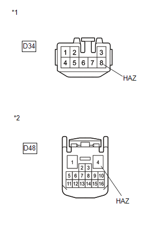
*1 |
Front view of wire harness connector (to Turn Signal Flasher) |
|
*2 |
Front view of wire harness connector (to Main Body ECU (Driver Side Junction Block Assembly)) |
| OK | |
REPLACE MAIN BODY ECU (DRIVER SIDE JUNCTION BLOCK ASSEMBLY) |
| NG | |
REPAIR OR REPLACE HARNESS OR CONNECTOR |
|
6. |
PERFORM ACTIVE TEST USING TECHSTREAM (WIRELESS DOOR LOCK BUZZER) |
(a) Connect the Techstream to the DLC3.
(b) Turn the engine switch on (IG).
(c) Enter the following menus: Body Electrical / Main Body / Active Test.
(d) Perform the Active Test according to the display on the Techstream.
Main Body (Main Body ECU (Driver Side Junction Block Assembly))|
Tester Display |
Test Part |
Control Range |
Diagnostic Note |
|---|---|---|---|
|
Wireless Buzzer |
Turns the wireless door lock buzzer |
ON/OFF |
- |
OK:
Wireless buzzer turns on/off.
| OK | |
REPLACE MAIN BODY ECU (DRIVER SIDE JUNCTION BLOCK ASSEMBLY) |
|
|
7. |
CHECK HARNESS AND CONNECTOR (WIRELESS DOOR LOCK BUZZER - MAIN BODY ECU) |
(a) Disconnect the D51 main body ECU connector.
(b) Disconnect the A28 buzzer connector.
(c) Measure the resistance according to the values in the table below.
Standard Resistance:
|
Tester Connection |
Condition |
Specified Condition |
|---|---|---|
|
D51-7 (BZR) - A28-1 |
Always |
Below 1 Ω |
|
A28-2 - Body ground |
Always |
Below 1 Ω |
|
A28-1 - Body ground |
Always |
10 kΩ or higher |
|
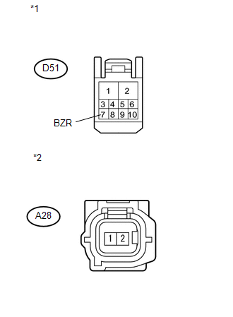
*1 |
Front view of wire harness connector (to Main Body ECU (Driver Side Junction Block Assembly)) |
|
*2 |
Front view of wire harness connector (to Wireless Door Lock Buzzer) |
| NG | |
REPAIR OR REPLACE HARNESS OR CONNECTOR |
|
|
8. |
REPLACE WIRELESS DOOR LOCK BUZZER |
(a) Temporarily replace the wireless door lock buzzer with a new one (See page
.gif) ).
).
|
|
9. |
CHECK WIRELESS DOOR LOCK BUZZER OPERATION |
(a) Check the operation of the wireless answer-back function.
OK:
Wireless answer-back function operates normally.
| OK | |
END (WIRELESS DOOR LOCK BUZZER WAS DEFECTIVE) |
| NG | |
REPLACE MAIN BODY ECU (DRIVER SIDE JUNCTION BLOCK ASSEMBLY) |
 Wireless Door Lock Tuner Circuit Malfunction (B1242)
DESCRIPTION
The door control receiver is used to receive electrical waves relating to the
entry functions of the smart key system. The certification ECU (smart key ECU assembly)
decodes the reque ...

Other materials about Toyota Venza:
Removal
REMOVAL
PROCEDURE
1. REMOVE REAR SEAT HEADREST ASSEMBLY
2. REMOVE REAR SEAT INNER TRACK BRACKET COVER
3. REMOVE REAR SEAT OUTER TRACK BRACKET COVER
4. DISCONNECT REAR SEAT NO. 2 RECLINING CONTROL CABLE SUB-ASSEMBLY
5. REMOVE REAR SEAT ASSEMBL ...
Diagnostic Trouble Code Chart
DIAGNOSTIC TROUBLE CODE CHART
HINT:
If a trouble code is stored during the DTC check, inspect the trouble areas listed
for that code. For details of the code, refer to "See page" below.
1. TRANSPONDER KEY ECU DIAGNOSTIC TROUBLE CODE CHART
Trans ...
Removal
REMOVAL
PROCEDURE
1. DISCONNECT CABLE FROM NEGATIVE BATTERY TERMINAL
NOTICE:
When disconnecting the cable, some systems need to be initialized after the cable
is reconnected (See page ).
2. REMOVE REAR DOOR INSIDE HANDLE BEZEL PLUG
3. REMOVE REAR P ...

0.1502