Toyota Venza: Disassembly
DISASSEMBLY
PROCEDURE
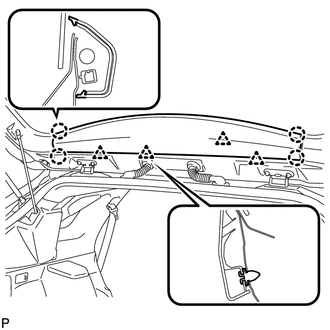
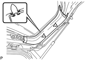
1. REMOVE UPPER BACK WINDOW PANEL TRIM
|
(a) Disengage the 4 clips and 4 claws, and remove the upper back window panel trim. |
|
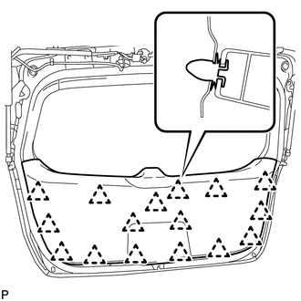
2. REMOVE BACK DOOR PANEL TRIM ASSEMBLY
|
(a) Disengage the 16 clips and remove the back door panel trim assembly. |
|
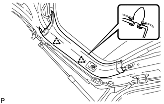
3. DISCONNECT POWER BACK DOOR ROD (w/ Power Back Door)
|
(a) Using a screwdriver, remove the stop ring along the groove. HINT: Tape the screwdriver tip before use. Text in Illustration
|
|
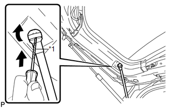
(b) Release the ball joint and disengage the power back door rod.
4. REMOVE BACK DOOR TRIM COVER LH (w/o Power Back Door)
|
(a) Disengage the 2 clips and remove the back door trim cover LH. |
|
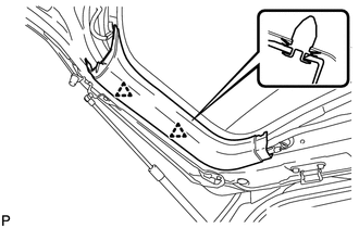
5. REMOVE BACK DOOR TRIM COVER LH (w/ Power Back Door)
|
(a) Disengage the 2 clips and remove the back door trim cover LH. |
|
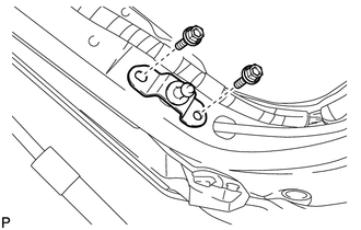
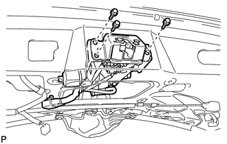
6. REMOVE UPPER BACK DOOR STAY BRACKET LH (w/ Power Back Door)
|
(a) Remove the 2 bolts and upper back door stay bracket LH. |
|
7. REMOVE BACK DOOR TRIM COVER RH
|
(a) Disengage the 2 clips and remove the back door trim cover RH. |
|
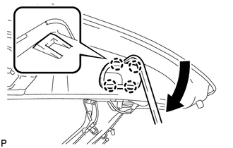
8. REMOVE DOOR PULL HANDLE
|
(a) Using a moulding remover, disengage the 4 claws and remove the back door pull handle as shown in the illustration. |
|
9. REMOVE POWER BACK DOOR CLOSER SWITCH ASSEMBLY (w/ Power Back Door)
.gif)
10. REMOVE BACK DOOR LOCK ASSEMBLY
|
(a) Disconnect the connector. |
|
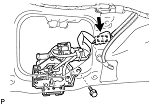
(b) Disengage the clamp.
(c) Remove the bolt.
|
(d) Remove the 3 bolts and back door lock assembly. |
|
11. REMOVE POWER BACK DOOR TOUCH SENSOR ASSEMBLY LH (w/ Power Back Door)
12. REMOVE POWER BACK DOOR TOUCH SENSOR ASSEMBLY RH (w/ Power Back Door)
HINT:
Use the same procedure for the RH side and LH side.
13. REMOVE BACK DOOR STAY ASSEMBLY LH
14. REMOVE BACK DOOR STAY ASSEMBLY RH
HINT:
Use the same procedure for the RH side and LH side.
15. REMOVE BACK DOOR LOWER DAMPER STAY BRACKET LH
16. REMOVE BACK DOOR LOWER DAMPER STAY BRACKET RH
HINT:
Use the same procedure for the RH side and LH side.
17. REMOVE POWER BACK DOOR WARNING BUZZER (w/ Power Back Door)
18. REMOVE AMPLIFIER ANTENNA ASSEMBLY
19. REMOVE REAR LIGHT ASSEMBLY LH
20. REMOVE REAR LIGHT ASSEMBLY RH
HINT:
Use the same procedure for the RH side and LH side.
21. REMOVE BACK DOOR OUTSIDE GARNISH SUB-ASSEMBLY
22. REMOVE LICENSE PLATE LIGHT ASSEMBLY
23. REMOVE REAR SPOILER ASSEMBLY
24. REMOVE REAR WASHER NOZZLE
25. REMOVE REAR WIPER ARM HEAD CAP
26. REMOVE REAR WIPER ARM AND BLADE ASSEMBLY
27. REMOVE REAR WIPER MOTOR GROMMET
28. REMOVE REAR WIPER MOTOR AND BRACKET ASSEMBLY
29. REMOVE ROOF HEADLINING ASSEMBLY
HINT:
Refer to the procedure up to Remove Roof Headlining Assembly (See page
).
30. REMOVE NO. 3 ANTENNA CORD SUB-ASSEMBLY
 Adjustment
ADJUSTMENT
CAUTION / NOTICE / HINT
HINT:
Use the same procedure for the RH side and LH side.
The following procedure is for the LH side.
Centering bolts are used to mount the do ...
 Reassembly
REASSEMBLY
PROCEDURE
1. INSTALL NO. 3 ANTENNA CORD SUB-ASSEMBLY
2. INSTALL ROOF HEADLINING ASSEMBLY
HINT:
Refer to the procedure from Install Roof Headlining Assembly (See page
).
3. INSTAL ...
Other materials about Toyota Venza:
Solar Sensor
Components
COMPONENTS
ILLUSTRATION
On-vehicle Inspection
ON-VEHICLE INSPECTION
PROCEDURE
1. INSPECT SOLAR SENSOR
(a) Disconnect the solar sensor connector.
(b) Measure the voltage accordin ...
Unmatched Encryption Code (B2794)
DESCRIPTION
This DTC is stored when a key with an incomplete key code is inserted into the
ignition key cylinder.
DTC No.
DTC Detection Condition
Trouble Area
B2794
Key with incomplete key code i ...
Multi-information display (LCD type)
The multi-information display presents the driver with a variety of driving-related
data, including the clock and current outside temperature.
• Clock
Indicates and sets the time.
• Outside temperature
Indicates the outside temperature.
The temper ...

0.1408