
Toyota Venza: Multi-information display (TFT type)
The multi-information display presents the driver with a variety of driving-related data, including the clock and current outside temperature.
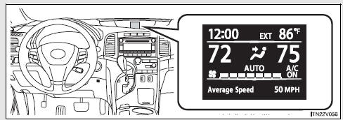
• Clock
Indicates and sets the time.
• Outside temperature
Indicates the outside temperature.
The temperature range that can be displayed is from -40°F (-40°C) to 122°F (50°C).
• Air conditioning system display
Automatically displayed when the air conditioning is turned on.
• Trip information
Displays driving range, fuel consumption and other cruising-related information.
• Intuitive parking assist display (if equipped)
• Warning messages
Automatically displayed when a malfunction occurs in one of the vehicle’s systems.
• Customizable features setting display
 Indicators and warning lights
The indicator and warning lights on the instrument cluster and center panel
inform the driver of the status of the vehicle’s various systems.
For the purpose of explanation, the following illustr ...
 Switching the display
1. “INFO” button
2. “SELECT RESET” button
To reset the functions below, press the “SELECT RESET” button.
• Average Fuel Economy
• Average Speed
• Trip Timer
3. “SETUP” bu ...
Other materials about Toyota Venza:
Precaution
PRECAUTION
NOTICE:
When disconnecting the cable from the negative (-) battery terminal, initialize
the following system after the cable is reconnected.
System Name
See Procedure
Back Door Closer System
...
Installation
INSTALLATION
PROCEDURE
1. INSTALL WINDSHIELD WIPER SWITCH ASSEMBLY
(a) Engage the claw to install the windshield wiper switch assembly as
shown in the illustration.
(b) Connect the 2 connectors. ...
Trailer towing
Your vehicle is designed primarily as a passenger-and-load-carrying vehicle.
Towing a trailer can have an adverse impact on handling, performance, braking, durability,
and fuel consumption. For your safety and the safety of others, you must not overload
...

0.1584