Toyota Venza: Knock Sensor
Components
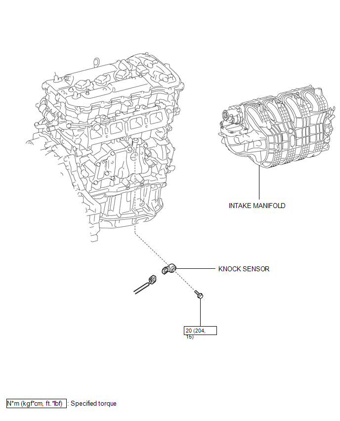
COMPONENTS
ILLUSTRATION
Removal
REMOVAL
PROCEDURE
1. REMOVE INTAKE MANIFOLD
(a) Remove the intake manifold (See page .gif) ).
).
2. REMOVE KNOCK SENSOR
|
(a) Disconnect the sensor connector. |
|
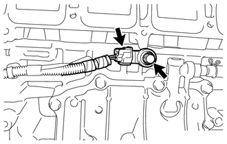
(b) Remove the bolt and sensor.
Inspection
INSPECTION
PROCEDURE
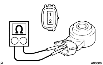
1. INSPECT KNOCK SENSOR
|
(a) Measure the resistance according to the value(s) in the table below. Standard Resistance:
If the result is not as specified, replace the knock sensor. |
|
Installation
INSTALLATION
PROCEDURE
1. INSTALL KNOCK SENSOR
|
(a) Install the sensor with the bolt so that the sensor is angled as shown in the illustration. Torque: 20 N·m {204 kgf·cm, 15 ft·lbf} NOTICE: The acceptable installation angle of the sensor is between 7° upward and 10° downward from the horizontal position. HINT: Perform "Inspection After Repair" after replacing the knock control sensor
(See page |
|

(b) Connect the sensor connector.
2. INSTALL INTAKE MANIFOLD
(a) Install the intake manifold (See page .gif)
).
 On-vehicle Inspection
ON-VEHICLE INSPECTION
PROCEDURE
1. PERFORM SPARK TEST
(a) Check for DTCs (See page ).
NOTICE:
If any DTC is output, perform troubleshooting procedures for that DTC.
(b) Remove the ignition coil ...
 Mass Air Flow Meter
Components
COMPONENTS
ILLUSTRATION
On-vehicle Inspection
ON-VEHICLE INSPECTION
CAUTION / NOTICE / HINT
NOTICE:
Perform the mass air flow meter inspection according to the procedur ...
Other materials about Toyota Venza:
Data List / Active Test
DATA LIST / ACTIVE TEST
1. DATA LIST
HINT:
Using the Techstream to read the Data List allows the values or states of switches,
sensors, actuators and other items to be read without removing any parts. This non-intrusive
inspection can be very useful bec ...
Data List / Active Test
DATA LIST / ACTIVE TEST
1. ACTIVE TEST
HINT:
Using the Techstream to perform Active Tests allows relays, VSVs, actuators and
other items to be operated without removing any parts. This non-intrusive functional
inspection can be very useful because inter ...
Operation Check
OPERATION CHECK
1. CHECK POWER DOOR LOCK CONTROL OPERATION
NOTICE:
The following procedure is based on the assumption that the functions have not
been customized using the Techstream.
(a) Check basic functions.
(1) Check that all doors lock when the loc ...

0.117