Toyota Venza: Main Body ECU Communication Stop Mode
DESCRIPTION
|
Detection Item |
Symptom |
Trouble Area |
|---|---|---|
|
Main Body ECU Communication Stop Mode |
|
|
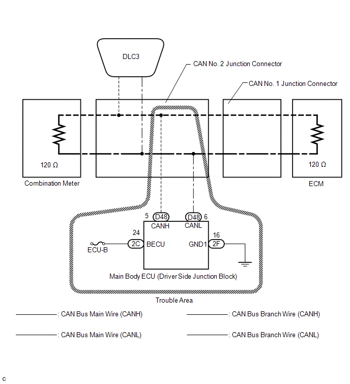
WIRING DIAGRAM
CAUTION / NOTICE / HINT
NOTICE:
- Turn the ignition switch off before measuring the resistances between CAN bus main wires and between CAN bus branch wires.
- Turn the ignition switch off before inspecting CAN bus wires for a ground short.
- After the ignition switch is turned off, check that the key reminder warning system and light reminder warning system are not operating.
- Before measuring the resistance, leave the vehicle as is for at least 1 minute and do not operate the ignition switch, any other switches or the doors. If any doors need to be opened in order to check connectors, open the doors and leave them open.
HINT:
- Operating the ignition switch, any other switches or a door triggers related ECU and sensor communication on the CAN. This communication will cause the resistance value to change.
- Even after DTCs are cleared, if a DTC is stored again after driving the vehicle for a while, the malfunction may be occurring due to vibration of the vehicle. In such a case, wiggling the ECUs or wire harness while performing the inspection below may help determine the cause of the malfunction.
PROCEDURE
|
1. |
CHECK CAN BUS WIRE FOR DISCONNECTION (MAIN BODY ECU BRANCH WIRE) |
(a) Turn the ignition switch off.
|
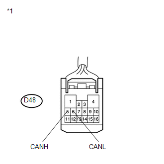
(b) Disconnect the connector of the main body ECU. Text in Illustration
|
|
(c) Measure the resistance according to the value(s) in the table below.
Standard Resistance:
|
Tester Connection |
Switch Condition |
Specified Condition |
|---|---|---|
|
D48-5 (CANH) - D48-6 (CANL) |
Ignition switch off |
54 to 69 Ω |
| NG | .gif) |
REPAIR OR REPLACE CAN BUS BRANCH WIRE OR CONNECTOR (MAIN BODY ECU BRANCH WIRE) |
|
.gif)
|
2. |
CHECK HARNESS AND CONNECTOR (POWER SOURCE TERMINAL) |
|
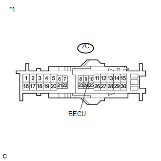
(a) Disconnect the connector of the driver side junction block. Text in Illustration
|
|
(b) Measure the voltage according to the value(s) in the table below.
Standard Voltage:
|
Tester Connection |
Condition |
Specified Condition |
|---|---|---|
|
2C-24 (BECU) - Body ground |
Always |
11 to 14 V |
| NG | |
REPAIR OR REPLACE HARNESS OR CONNECTOR (POWER SOURCE CIRCUIT) |
|
|
3. |
CHECK HARNESS AND CONNECTOR (GROUND TERMINAL) |
|
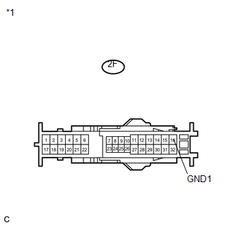
(a) Disconnect the connector of the driver side junction block. Text in Illustration
|
|
(b) Measure the resistance according to the value(s) in the table below.
Standard Resistance:
|
Tester Connection |
Condition |
Specified Condition |
|---|---|---|
|
2F-16 (GND1) - Body ground |
Always |
Below 1 Ω |
| OK | |
REPLACE MAIN BODY ECU (DRIVER SIDE JUNCTION BLOCK) |
| NG | |
REPAIR OR REPLACE HARNESS OR CONNECTOR (GROUND CIRCUIT) |
 ECM Communication Stop Mode
DESCRIPTION
Detection Item
Symptom
Trouble Area
ECM Communication Stop Mode
"Engine" and "ECT" are not disp ...
 Power Management Control ECU Communication Stop Mode
DESCRIPTION
Detection Item
Symptom
Trouble Area
Power Management Control ECU Communication Stop Mode
"Electric Power Contr ...
Other materials about Toyota Venza:
Removal
REMOVAL
PROCEDURE
1. DISCONNECT CABLE FROM NEGATIVE BATTERY TERMINAL
CAUTION:
Wait at least 90 seconds after disconnecting the cable from the negative (-)
battery terminal to disable the SRS system.
NOTICE:
When disconnecting the cable, some systems ne ...
Removal
REMOVAL
PROCEDURE
1. REMOVE FRONT WHEELS
2. REMOVE FRONT STABILIZER LINK ASSEMBLY LH
(a) Remove the 2 nuts and front stabilizer link assembly LH.
HINT:
If the ball joint turns together with the nut, use a hexagon wrench (6
mm) to hold ...
Installation
INSTALLATION
PROCEDURE
1. INSTALL REAR SEAT ASSEMBLY RH
(a) Place the rear seat assembly RH in the cabin.
NOTICE:
Be careful not to damage the vehicle body.
(b) Temporarily install the 2 bolts on the front side of the seat.
...

0.1302