Toyota Venza: Light Sensor Circuit Malfunction (B1244)
DESCRIPTION
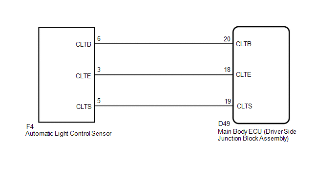
The automatic light control sensor detects ambient light, converts it into an electrical signal, and outputs it to the main body ECU (driver side junction block assembly). The main body ECU (driver side junction block assembly) turns on or off the headlights and taillights according to the signal.
|
DTC No. |
DTC Detecting Condition |
Trouble Area |
|---|---|---|
|
B1244 |
|
|
WIRING DIAGRAM
PROCEDURE
|
1. |
READ VALUE USING TECHSTREAM |
(a) Connect the Techstream to the DLC3.
(b) Turn the ignition switch to ON.
(c) Turn the Techstream on.
(d) Select the following menu items: Body Electrical / Main Body / Data List.
(e) Read the display on Techstream.
Main Body|
Tester Display |
Measurement Item/Range |
Normal Condition |
Diagnostic Note |
|---|---|---|---|
|
Illumination Rate Info |
Illumination rate information/0 ms to 99.99 ms |
Value is output according to ambient light levels |
- |
OK:
Normal condition listed above is displayed.
| OK | .gif) |
REPLACE MAIN BODY ECU (DRIVER SIDE JUNCTION BLOCK ASSEMBLY) |
|
.gif)
|
2. |
CHECK HARNESS AND CONNECTOR (MAIN BODY ECU - AUTOMATIC LIGHT CONTROL SENSOR) |
(a) Disconnect the F4 automatic light control sensor connector.
(b) Disconnect the D49 main body ECU (driver side junction block assembly) connector.
(c) Measure the resistance according to the value(s) in the table below.
Standard Resistance:
|
Tester Connection |
Condition |
Specified Condition |
|---|---|---|
|
D49-18 (CLTE) - F4-3 (CLTE) |
Always |
Below 1 Ω |
|
D49-19 (CLTS) - F4-5 (CLTS) |
Always |
Below 1 Ω |
|
D49-20 (CLTB) - F4-6 (CLTB) |
Always |
Below 1 Ω |
|
D49-18 (CLTE) - Body ground |
Always |
10 kΩ or higher |
|
D49-19 (CLTS) - Body ground |
Always |
10 kΩ or higher |
|
D49-20 (CLTB) - Body ground |
Always |
10 kΩ or higher |
| NG | |
REPAIR OR REPLACE HARNESS OR CONNECTOR |
|
|
3. |
INSPECT MAIN BODY ECU (DRIVER SIDE JUNCTION BLOCK ASSEMBLY) |
(a) Reconnect the D49 main body ECU (driver side junction block assembly) connector.
(b) Measure the voltage and resistance according to the value(s) in the table below.
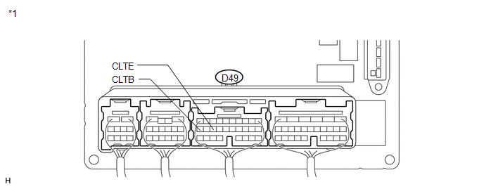 Text in Illustration
|
*1 |
Component with harness connected (Main Body ECU (Driver Side Junction Block Assembly)) |
- |
- |
Standard Voltage:
|
Tester Connection |
Condition |
Specified Condition |
|---|---|---|
|
D49-20 (CLTB) - D49-18 (CLTE) |
Ignition switch off |
Below 1 V |
|
Ignition switch ON |
11 to 14 V |
Standard Resistance:
|
Tester Connection |
Condition |
Specified Condition |
|---|---|---|
|
D49-18 (CLTE) - Body ground |
Always |
Below 1 Ω |
| NG | |
REPLACE MAIN BODY ECU (DRIVER SIDE JUNCTION BLOCK ASSEMBLY) |
|
|
4. |
INSPECT AUTOMATIC LIGHT CONTROL SENSOR |
|
(a) Reconnect the F4 automatic light control sensor connector. |
|
.png)
(b) Connect an oscilloscope to the automatic light control sensor connector.
Text in Illustration|
*1 |
Component with harness connected (Automatic Light Control Sensor) |
|
(c) Check the waveform. OK:
HINT: If the ambient light becomes brighter, width A becomes narrower. |
|
.png)
| OK | |
REPLACE MAIN BODY ECU (DRIVER SIDE JUNCTION BLOCK ASSEMBLY) |
| NG | |
REPLACE AUTOMATIC LIGHT CONTROL SENSOR |
 Variation Error (B2453)
DESCRIPTION
This DTC is stored if the headlight leveling ECU assembly for another destination
is installed on the vehicle.
DTC No.
DTC Detecting Condition
Trouble ...
 Lost Communication with ECM (U0101,U0073,U0126,U0129,U0142,U0182,U1000)
DESCRIPTION
The DTCs are stored when the CAN communication system is malfunctioning.
DTC No.
DTC Detection Condition
Trouble Area
U0101
L ...
Other materials about Toyota Venza:
Does not Play even after Bluetooth Audio Mode is Selected
CAUTION / NOTICE / HINT
HINT:
Even if the portable player can play audio content, it may not be able to play
via the in-vehicle device. This does not necessarily indicate a malfunction of the
in-vehicle device.
PROCEDURE
1.
CHECK ...
Disassembly
DISASSEMBLY
PROCEDURE
1. REMOVE STEERING RACK BOOT CLIP (for LH Side)
(a) Using pliers, remove the steering rack boot clip.
2. REMOVE STEERING RACK BOOT CLIP (for RH Side)
HINT:
Perform the same procedure as for the LH side.
3. REMOVE NO. 2 STEERING RAC ...
Components
COMPONENTS
ILLUSTRATION
ILLUSTRATION
ILLUSTRATION
ILLUSTRATION
ILLUSTRATION
ILLUSTRATION
...

0.139