Toyota Venza: LIN Communication Master Malfunction (B2287)
DESCRIPTION
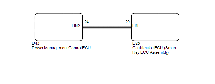
This DTC is stored when there is an open, short or ECU communication malfunction between the power management control ECU and certification ECU (smart key ECU assembly).
|
DTC No. |
DTC Detection Condition |
Trouble Area |
|---|---|---|
|
B2287 |
There is an open, short or ECU communication malfunction between the power management control ECU and certification ECU (smart key ECU assembly). |
|
WIRING DIAGRAM
CAUTION / NOTICE / HINT
NOTICE:
- If the certification ECU (smart key ECU assembly) is replaced, register the key.
- When using the Techstream to troubleshoot with the ignition switch off:
Connect the Techstream to the DLC3, and turn the courtesy switch on and off at 1.5-second intervals until communication between the Techstream and vehicle begins.
PROCEDURE
|
1. |
CHECK DTC OUTPUT |
(a) Clear the DTC (See page .gif) ).
).
(b) Recheck for DTCs.
HINT:
Check for certification ECU and power source control ECU DTCs.
|
Result |
Proceed to |
|---|---|
|
Only DTC B2287 is output. |
A |
|
DTC B2287 and B2785 are output simultaneously. |
B |
HINT:
When DTC B2287 and B2785 are output simultaneously, perform troubleshooting for DTC B2785 first.
| B | .gif) |
GO TO DTC B2785 |
|
.gif)
|
2. |
CHECK HARNESS AND CONNECTOR (CERTIFICATION ECU - POWER MANAGEMENT CONTROL ECU) |
|
(a) Disconnect the D25 and D43 ECU connectors. |
|
(b) Measure the resistance according to the value(s) in the table below.
Standard Resistance:
|
Tester Connection |
Condition |
Specified Condition |
|---|---|---|
|
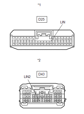
D25-29 (LIN) - D43-24 (LIN2) |
Always |
Below 1 Ω |
|
D25-29 (LIN) - Body ground |
Always |
10 kΩ or higher |
|
*1 |
Front view of wire harness connector (to Certification ECU (Smart Key ECU Assembly) |
|
*2 |
Front view of wire harness connector (to Power Management Control ECU) |
| NG | |
REPAIR OR REPLACE HARNESS OR CONNECTOR |
|
|
3. |
REPLACE POWER MANAGEMENT CONTROL ECU |
(a) Replace the power management control ECU (See page
).
|
|
4. |
CHECK DTC OUTPUT |
(a) Clear the DTC (See page ).
(b) Recheck for DTCs.
OK:
DTC B2287 is not output.
| OK | |
END (POWER MANAGEMENT CONTROL ECU WAS DEFECTIVE) |
| NG | |
REPLACE CERTIFICATION ECU (SMART KEY ECU ASSEMBLY) |
 Sliding Roof ECU Communication Stop (B1273)
DESCRIPTION
This DTC is stored when LIN communication between the sliding roof ECU (sliding
roof drive gear sub-assembly) and main body ECU (driver side junction block assembly)
stops for more th ...
 Lost Communication with AFS LIN (B124D)
DESCRIPTION
Refer to DTC B124D (Lighting system) (See page
).
DTC No.
DTC Detection Condition
Trouble Area
B124D
Malfunctions in LIN co ...
Other materials about Toyota Venza:
On-vehicle Inspection
ON-VEHICLE INSPECTION
PROCEDURE
1. INSPECT PARK/NEUTRAL POSITION SWITCH ASSEMBLY OPERATION
(a) Apply the parking brake.
(b) Turn the ignition switch to ON.
(c) Depress the brake pedal and check that the engine starts when the shift lever
is in N or P, b ...
Disassembly
DISASSEMBLY
PROCEDURE
1. REMOVE SLIDING ROOF HOUSING CENTER FRAME
(a) Remove the 2 nuts and sliding roof housing center frame.
2. REMOVE NO. 4 SUNSHADE TRIM SUB-ASSEMBLY
(a) Remove the s ...
Front Seat Inner Belt Assembly
Components
COMPONENTS
ILLUSTRATION
ILLUSTRATION
Inspection
INSPECTION
PROCEDURE
1. INSPECT FRONT SEAT INNER BELT ASSEMBLY LH (w/ Seat Position Memory System)
(a) Measure the resistance according to the value(s) in the table below.
...

0.1363