Toyota Venza: Air Conditioning Amplifier Communication Stop Mode
DESCRIPTION
|
Detection Item |
Symptom |
Trouble Area |
|---|---|---|
|
Air Conditioning Amplifier Communication Stop Mode |
|
|
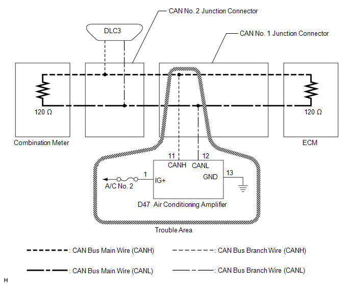
WIRING DIAGRAM
CAUTION / NOTICE / HINT
NOTICE:
- Turn the ignition switch off before measuring the resistances between CAN bus main wires and between CAN bus branch wires.
- Turn the ignition switch off before inspecting CAN bus wires for a ground short.
- After the ignition switch is turned off, check that the key reminder warning system and light reminder warning system are not operating.
- Before measuring the resistance, leave the vehicle as is for at least 1 minute and do not operate the ignition switch, any other switches or the doors. If any doors need to be opened in order to check connectors, open the doors and leave them open.
HINT:
- Operating the ignition switch, any other switches or a door triggers related ECU and sensor communication on the CAN. This communication will cause the resistance value to change.
- Even after DTCs are cleared, if a DTC is stored again after driving the vehicle for a while, the malfunction may be occurring due to vibration of the vehicle. In such a case, wiggling the ECUs or wire harness while performing the inspection below may help determine the cause of the malfunction.
PROCEDURE
|
1. |
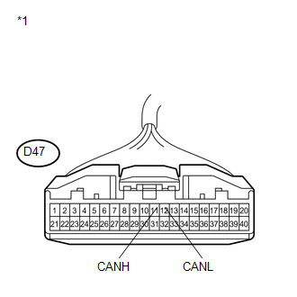
CHECK CAN BUS WIRE FOR DISCONNECTION (AIR CONDITIONING AMPLIFIER BRANCH WIRE) |
(a) Turn the ignition switch off.
|
(b) Disconnect the connector of the air conditioning amplifier. Text in Illustration
|
|
(c) Measure the resistance according to the value(s) in the table below.
Standard Resistance:
|
Tester Connection |
Switch Condition |
Specified Condition |
|---|---|---|
|
D47-11 (CANH) - D47-12 (CANL) |
Ignition switch off |
54 to 69 Ω |
| NG | .gif) |
REPAIR OR REPLACE CAN BUS BRANCH WIRE OR CONNECTOR (AIR CONDITIONING AMPLIFIER BRANCH WIRE) |
|
.gif)
|
2. |
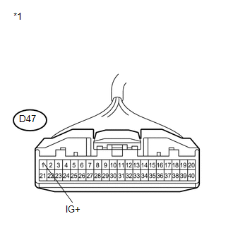
CHECK HARNESS AND CONNECTOR (POWER SOURCE TERMINAL) |
(a) Turn the ignition switch to ON.
|
(b) Measure the voltage according to the value(s) in the table below. Standard Voltage:
|
|
| NG | |
REPAIR OR REPLACE HARNESS OR CONNECTOR (POWER SOURCE CIRCUIT) |
|
|
3. |
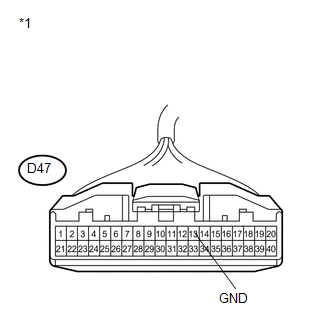
CHECK HARNESS AND CONNECTOR (GROUND TERMINAL) |
(a) Turn the ignition switch off.
|
(b) Measure the resistance according to the value(s) in the table below. Standard Resistance:
|
|
| OK | |
REPLACE AIR CONDITIONING AMPLIFIER |
| NG | |
REPAIR OR REPLACE HARNESS OR CONNECTOR (GROUND CIRCUIT) |
 Lost Communication with A/C ECU (U0164)
DESCRIPTION
DTC No.
DTC Detection Condition
Trouble Area
U0164
No communication from the air conditioning amplifier continues.
...
 Skid Control ECU Communication Stop Mode
DESCRIPTION
Detection Item
Symptom
Trouble Area
Skid Control ECU Communication Stop Mode
"ABS/VSC/TRAC" is not displa ...
Other materials about Toyota Venza:
Throttle / Pedal Position Sensor / Switch "D" Circuit (P2120,P2122,P2123,P2125,P2127,P2128,P2138)
DESCRIPTION
HINT:
This Electronic Throttle Control System (ETCS) does not use a throttle
cable.
These DTCs relate to the accelerator pedal sensor assembly.
The accelerator pedal sensor assembly is mounted on the accelerator pedal brack ...
Lost Communication with ECM (U0100-U0142,U0155)
DESCRIPTION
DTC No.
DTC Detecting Condition
Trouble Area
U0100
No communication with ECM
CAN communication system
ECM
U0131
No commu ...
Microphone
Components
COMPONENTS
ILLUSTRATION
Removal
REMOVAL
PROCEDURE
1. REMOVE INNER REAR VIEW MIRROR STAY HOLDER COVER
2. REMOVE TELEPHONE MICROPHONE ASSEMBLY (INNER REAR VIEW MIRROR ASSEMBLY)
Installation
INSTALLATION
PROCEDURE
1. INSTALL TE ...

0.1373