Toyota Venza: Gauges and meters
►Vehicles with smart key system The following gauges, meters and display illuminate when the “ENGINE START STOP” switch is in IGNITION ON mode.
►Vehicles without smart key system The following gauges, meters and displays illuminate when the engine switch is in the “ON” position.
1. Tachometer
Displays the engine speed in revolutions per minute.
2. Speedometer
Displays the vehicle speed.
3. Fuel gauge
Displays the quantity of fuel remaining in the tank.
4. Engine coolant temperature gauge Displays the engine coolant temperature.
5. Odometer/trip meter and trip meter reset button Switches between odometer and trip meter displays. Pushing and holding the button will reset the trip meter when the trip meter is being displayed.
6. Odometer and trip meter Odometer: Displays the total distance the vehicle has been driven.
Trip meter: Displays the distance the vehicle has been driven since the meter was last reset. Trip meters A and B can be used to record and display different distances independently.
Instrument panel light control
The brightness of the instrument panel lights can be adjusted.
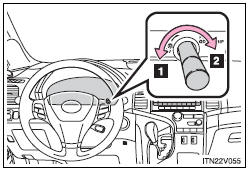
1. Darker
2. Brighter
NOTICE
- To prevent damage to the engine and its components
• Do not let the indicator needle of the tachometer enter the red zone, which indicates the maximum engine speed.
• The engine may be overheating if the engine coolant temperature gauge is in the red zone (“H”). In this case, immediately stop the vehicle in a safe place, and check the engine after it has cooled completely.

 Indicators and warning lights
The indicator and warning lights on the instrument cluster and center panel
inform the driver of the status of the vehicle’s various systems.
For the purpose of explanation, the following illustr ...
Other materials about Toyota Venza:
Control Module Performance (P0607)
MONITOR DESCRIPTION
The ECM continuously monitors its internal processors (CPUs) and heated oxygen
sensor transistors. This self-check ensures that the ECM is functioning properly.
DTC No.
DTC Detection Condition
Trouble Ar ...
Starting the engine
Shift the shift lever to “P” and
apply the brakes.
Touch the Toyota emblem side of the electronic key to the “ENGINE START STOP”
switch.
An alarm will sound to indicate that the start function cannot detect the electronic
key that is touched ...
Installation
INSTALLATION
PROCEDURE
1. INSTALL BRAKE PEDAL SUPPORT ASSEMBLY
(a) Install the brake pedal support assembly to the instrument panel
reinforcement with the bolt.
Torque:
19 N·m {195 kgf·cm, 14 ft·lbf}
...

0.1659