Toyota Venza: Installation
INSTALLATION
PROCEDURE
1. INSPECT TORQUE CONVERTER ASSEMBLY
.gif)
2. INSTALL TORQUE CONVERTER ASSEMBLY
|
(a) Engage the splines of the input shaft and turbine runner. |
|
.png)
|
(b) Engage the splines of the stator shaft and the stator while turning the torque converter assembly. HINT: If the stator shaft splines are difficult to engage with the stator splines, move the torque converter assembly back approximately 10 mm and engage the splines while rotating the torque converter assembly. |
|
.png)
|
(c) Turn the torque converter assembly to engage the key of the oil pump drive gear into the slot on the torque converter assembly. |
|
.png)
|
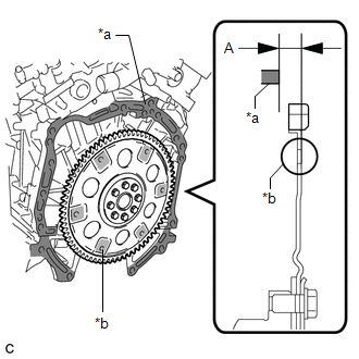
(d) Using a vernier caliper and straightedge, measure the dimension (A) between the automatic transaxle assembly contact surface of the engine assembly*a and the torque converter assembly contact surfaces of the drive plate*b. Text in Illustration
NOTICE: Make sure to deduct the thickness of the straightedge. |
|
|
(e) Using a vernier caliper and straightedge, measure the dimension (B) shown in the illustration and check that the dimension (B) is more than the dimension (A), which was measured in the previous step. Standard: Dimension (A) + 1 mm (0.0394 in.) or more NOTICE:
HINT: If a U660E is used with a 2GR-FE, the standard installation depth is 14 mm (0.551 in.) or more. |
|
.png)
3. INSTALL SPEEDOMETER DRIVEN HOLE (ATM) COVER SUB-ASSEMBLY
(a) Apply ATF to a new O-ring and install it to the speedometer driven hole (ATM) cover sub-assembly.
(b) Install the speedometer driven hole (ATM) cover sub-assembly to the automatic transaxle assembly with the bolt.
Torque:
5.5 N·m {56 kgf·cm, 49 in·lbf}
4. INSTALL NO. 1 TRANSMISSION CONTROL CABLE BRACKET
(a) Install the No. 1 transmission control cable bracket to the automatic transaxle assembly with the 2 bolts.
Torque:
12 N·m {122 kgf·cm, 9 ft·lbf}
5. INSTALL WIRE HARNESS CLAMP BRACKET
(a) Install the 4 wire harness clamp brackets to the automatic transaxle assembly with the 4 bolts.
Torque:
8.4 N·m {86 kgf·cm, 74 in·lbf}
6. INSTALL FRONT ENGINE MOUNTING BRACKET
(a) Install the front engine mounting bracket to the automatic transaxle assembly with the 3 bolts.
Torque:
64 N·m {653 kgf·cm, 47 ft·lbf}
7. SUPPORT ENGINE ASSEMBLY
|
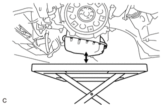
(a) Set an engine lifter. NOTICE: Make sure that there is a clearance between the engine oil pan assembly and engine lifter. |
|
8. INSTALL AUTOMATIC TRANSAXLE ASSEMBLY
|
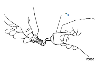
(a) Apply clutch spline grease to the circumference of the crankshaft contact surface of the torque converter assembly centerpiece. Text in Illustration
Clutch Spline Grease: Toyota Genuine Clutch Spline Grease or equivalent Maximum Spread: About 1 g (0.0353 oz) |
|
.png)
|
(b) While keeping the engine assembly and automatic transaxle assembly in a horizontal position, align the 2 knock pins with each hole on the automatic transaxle assembly and tighten the 10 bolts shown in the illustration. Torque: Bolt (A) : 64 N·m {653 kgf·cm, 47 ft·lbf} Bolt (B) : 64 N·m {653 kgf·cm, 47 ft·lbf} Bolt (C) : 43 N·m {439 kgf·cm, 32 ft·lbf} NOTICE:
HINT: Bolt Length:
|
|
.png)
(c) Clean and degrease the bolt and installation hole in the automatic transaxle assembly.
|
(d) Apply adhesive to 2 or 3 threads on the end of the bolt. Text in Illustration
Adhesive: Toyota Genuine Adhesive 1344, Three Bond 1344 or equivalent |
|
|
(e) Install the bolt. Torque: Bolt (D) : 46 N·m {469 kgf·cm, 34 ft·lbf} HINT: Bolt Length:
|
|
.png)
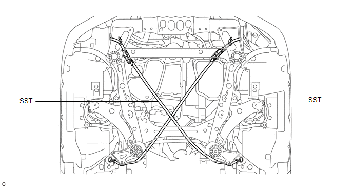
9. INSTALL BELT
(a) Install SST to the vehicle body as shown in the illustration.
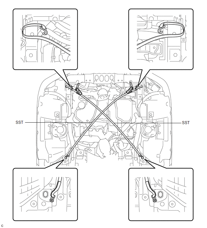
SST: 09727-00110
(b) Using the SST ratchet buckle, tighten the SST belt until there is no slack.
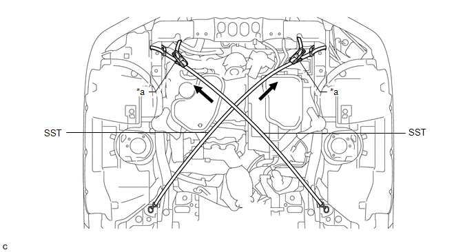 Text in Illustration
|
*a |
Ratchet Buckle |
- |
- |
10. CONNECT INLET NO. 1 OIL COOLER HOSE
(a) Connect the inlet No. 1 oil cooler hose and slide the clip to secure it.
11. CONNECT OUTLET NO. 1 OIL COOLER HOSE
(a) Connect the outlet No. 1 oil cooler hose and slide the clip to secure it.
12. INSTALL ENGINE MOUNTING INSULATOR LH
(a) Install the engine mounting insulator LH to the automatic transaxle assembly with the nut.
Torque:
95 N·m {968 kgf·cm, 70 ft·lbf}
13. INSTALL FRONT ENGINE MOUNTING INSULATOR ASSEMBLY
(a) Install the front engine mounting insulator assembly to the front engine mounting bracket with the bolt.
Torque:
87 N·m {887 kgf·cm, 64 ft·lbf}
14. REMOVE SUPPORT BAR
(a) Remove the bolt from the engine mounting bracket RH.
(b) Remove the 2 bolts and SST (support bar) from the vehicle body.
15. INSTALL ENGINE MOUNTING INSULATOR RH
(a) Install the engine mounting insulator RH to the engine mounting bracket RH with the nut.
Torque:
95 N·m {968 kgf·cm, 70 ft·lbf}
16. INSTALL FRONT FRAME ASSEMBLY
See page
17. REMOVE BELT
(a) Remove SST from the vehicle body.
(b) Connect the windshield washer jar assembly to the vehicle body and tighten the nut.
Torque:
5.5 N·m {56 kgf·cm, 49 in·lbf}
(c) Install the 2 bolts.
Torque:
5.5 N·m {56 kgf·cm, 49 in·lbf}
18. REMOVE ENGINE SUPPORT BRIDGE
(a) Remove SST from the vehicle body.
NOTICE:
Prevent SST from contacting the vehicle body or windshield.
(b) Connect the engine wire to the engine assembly.
(c) Engage the clamp and install the nut and 3 bolts to the engine wire.
Torque:
Bolt :
8.4 N·m {86 kgf·cm, 74 in·lbf}
Nut :
10 N·m {102 kgf·cm, 7 ft·lbf}
(d) Connect the air conditioner tube and accessory assembly with the bolt.
Torque:
9.8 N·m {100 kgf·cm, 87 in·lbf}
(e) Install the tank cap sub-assembly with the bolt.
Torque:
5.5 N·m {56 kgf·cm, 49 in·lbf}
19. REMOVE ENGINE HANGERS
(a) Remove the 4 bolts and No. 1 and No. 2 engine hangers from the engine assembly.
20. CONNECT NO. 1 RADIATOR HOSE
21. INSTALL FRONT FLOOR BRACE
22. INSTALL DRIVE PLATE AND TORQUE CONVERTER ASSEMBLY SETTING BOLT
23. INSTALL FLYWHEEL HOUSING UNDER COVER
24. INSTALL NO. 1 EXHAUST PIPE SUPPORT BRACKET
25. INSTALL FRONT DRIVE SHAFT ASSEMBLY
See page
26. INSTALL MANIFOLD STAY
27. INSTALL FRONT EXHAUST PIPE ASSEMBLY
See page
28. INSTALL FLEXIBLE HOSE BRACKET SUB-ASSEMBLY
(a) Install the flexible hose bracket sub-assembly to the camshaft housing sub-assembly LH with the bolt.
Torque:
5.5 N·m {56 kgf·cm, 49 in·lbf}
(b) Connect the No. 1 breather plug (ATM) to the flexible hose bracket sub-assembly.
29. CONNECT WIRE HARNESS
(a) Connect the clamp and connector.
|
(b) Connect the 7 wire harness clamps and park/neutral position switch assembly connector. |
|
.png)
(c) Install the 2 wire harnesses to the automatic transaxle assembly with the 2 bolts.
Torque:
Bolt (A) :
12 N·m {122 kgf·cm, 9 ft·lbf}
Bolt (B) :
8.4 N·m {86 kgf·cm, 74 in·lbf}
30. INSTALL STARTER ASSEMBLY
31. INSTALL TCM
32. CONNECT TRANSMISSION CONTROL CABLE ASSEMBLY
33. INSTALL ECM
34. INSTALL INTAKE AIR SURGE TANK ASSEMBLY
See page
35. INSTALL INLET NO. 1 AIR CLEANER
36. INSTALL BATTERY
37. INSTALL AIR CLEANER CASE
38. INSTALL AIR CLEANER CAP WITH HOSE
39. INSTALL INLET NO. 2 AIR CLEANER
40. INSPECT VACUUM HOSES
41. ADD ENGINE COOLANT
42. CONNECT CABLE TO NEGATIVE BATTERY TERMINAL
NOTICE:
When disconnecting the cable, some systems need to be initialized after the cable
is reconnected (See page ).
43. ADD AUTOMATIC TRANSAXLE FLUID
See page
44. WARM UP ENGINE
45. INSPECT FOR COOLANT LEAK
46. INSPECT ENGINE COOLANT LEVEL IN RESERVOIR
47. INSPECT FOR OIL LEAK
48. INSPECT FOR EXHAUST GAS LEAK
49. INSTALL FRONT FENDER APRON RH
50. INSTALL FRONT FENDER APRON LH
51. INSTALL NO. 2 ENGINE UNDER COVER
52. INSTALL NO. 1 ENGINE UNDER COVER
53. INSTALL FRONT WHEELS
54. INSPECT AND ADJUST SHIFT LEVER POSITION
55. INSPECT AND ADJUST FRONT WHEEL ALIGNMENT
See page
56. INSTALL V-BANK COVER SUB-ASSEMBLY
57. INSTALL COOL AIR INTAKE DUCT SEAL
58. INSPECT SPEED SENSOR SIGNAL
See page
59. CHECK AUTOMATIC TRANSAXLE SYSTEM
NOTICE:
If automatic transaxle assembly parts have been replaced, refer to Parts Replacement
Compensation Table to determine if any additional operations are necessary (See
page ).
 Removal
REMOVAL
CAUTION / NOTICE / HINT
NOTICE:
If automatic transaxle assembly parts are replaced, refer to Parts Replacement
Compensation Table to determine if any additional operations are necessary ( ...

Other materials about Toyota Venza:
Disposal
DISPOSAL
CAUTION / NOTICE / HINT
CAUTION:
Before performing pre-disposal deployment of any SRS component, review and closely
follow all applicable environmental and hazardous material regulations. Pre-disposal
deployment may be considered hazardous mate ...
Installation
INSTALLATION
PROCEDURE
1. INSTALL CENTER AIRBAG SENSOR ASSEMBLY
(a) Check that the ignition switch is off.
(b) Check that the cable is disconnected from the negative (-) battery terminal.
CAUTION:
Wait at least 90 seconds after disconnecting the cable fr ...
Definition Of Terms
DEFINITION OF TERMS
Term
Definition
Monitor Description
Description of what the ECM monitors and how it detects malfunctions
(monitoring purpose and details).
Related DTCs
Group ...

0.1588