Toyota Venza: Installation
INSTALLATION
CAUTION / NOTICE / HINT
HINT:
- Use the same procedure for the LH side and RH side.
- The following procedure is for the LH side.
- If the sensor rotor needs to be replaced, replace it together with the front drive shaft assembly.
PROCEDURE
1. INSTALL FRONT SPEED SENSOR
|
(a) Install the resin clamp and front speed sensor with the bolt. Torque: 8.5 N·m {87 kgf·cm, 75 in·lbf} NOTICE:
|
|
|
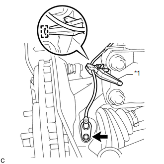
(b) Temporarily install the No. 1 sensor clamp. NOTICE: Be sure to insert the No. 1 sensor clamp claw into the stopper hole while installing the No. 1 sensor clamp. Text in Illustration
|
|
|
(c) Install the front brake flexible hose and No. 1 sensor clamp together to the shock absorber with the bolt. Torque: 19 N·m {194 kgf·cm, 14 ft·lbf} NOTICE:
|
|
|
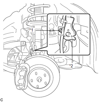
(d) Install the No. 2 sensor clamp to the body with the bolt. Torque: 8.0 N·m {82 kgf·cm, 71 in·lbf} Text in Illustration
|
|
.png)
|
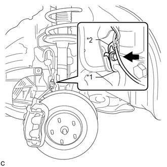
(e) Install the 2 clamps and connect the front speed sensor connector. |
|
.png)
2. INSTALL FRONT FENDER LINER LH
.gif)
3. INSTALL FRONT FENDER OUTSIDE MOULDING LH
4. INSTALL FRONT WHEEL
Torque:
103 N·m {1050 kgf·cm, 76 ft·lbf}
5. CONNECT CABLE TO NEGATIVE BATTERY TERMINAL
NOTICE:
When disconnecting the cable, some systems need to be initialized after the cable
is reconnected (See page ).
6. CHECK FOR SPEED SENSOR SIGNAL
HINT:
(See page )
 Removal
REMOVAL
CAUTION / NOTICE / HINT
HINT:
Use the same procedure for the LH side and RH side.
The following procedure is for the LH side.
If the sensor rotor needs to be replaced, repla ...

Other materials about Toyota Venza:
System Description
SYSTEM DESCRIPTION
1. TOUCH SWITCH OUTLINE
(a) Touch switches are touch-sensitive (interactive) switches operated by touching
the screen. When a switch is pressed, the outer film bends in to contact the inner
glass at the pressed position. By doing this, ...
Rear Door LH ECU Communication Stop (B2324)
DESCRIPTION
This DTC is stored when LIN communication between the power window regulator
motor assembly (for rear LH side) and main body ECU (driver side junction block
assembly) stops for more than 10 seconds.
DTC No.
DTC Detection ...
Outer Rear View Mirror Glass
Components
COMPONENTS
ILLUSTRATION
Inspection
INSPECTION
PROCEDURE
1. INSPECT OUTER MIRROR RH
(a) Check the outer mirror heater operation.
(1) Measure the resistance according to the value(s) in the table below.
Standard Resistanc ...

0.1548