Toyota Venza: Installation
INSTALLATION
PROCEDURE
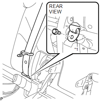
1. INSTALL REAR CENTER SEAT OUTER BELT ASSEMBLY
|
(a) Install the rear center seat outer belt assembly with the bolt and nut. Torque: Bolt : 7.5 N·m {77 kgf·cm, 66 in·lbf} Nut : 42 N·m {428 kgf·cm, 31 ft·lbf} |
|
.png)
2. INSTALL REAR SEATBACK COVER WITH PAD
.gif)
3. INSTALL REAR SEAT CENTER HEADREST SUPPORT RH
4. INSTALL REAR SEAT CENTER HEADREST SUPPORT LH
5. INSTALL REAR SEAT HEADREST SUPPORT RH
6. INSTALL REAR SEAT HEADREST SUPPORT LH
7. INSTALL REAR SEAT SHOULDER BELT COVER
|
(a) Engage the 2 guides and claw, and install the rear seat shoulder cover as shown in the illustration. |
|
.png)
|
(b) Engage the 2 guides as shown in the illustration. |
|
.png)
|
(c) Connect the rear seatback upper lock bezel with the screw. |
|
.png)
8. INSTALL REAR SEATBACK BOARD RH
9. CONNECT REAR CENTER SEAT OUTER BELT ASSEMBLY
|
(a) Connect the rear center seat outer belt with the bolt. Text in Illustration
Torque: 42 N·m {428 kgf·cm, 31 ft·lbf} |
|
10. INSTALL REAR SEAT CUSHION COVER WITH PAD
11. INSTALL REAR SEAT CENTER ARMREST ASSEMBLY
12. INSTALL REAR SEAT RECLINING COVER RH
13. INSTALL CENTER SEAT HINGE COVER RH
14. INSTALL REAR SEAT INNER RECLINING COVER RH
15. INSTALL REAR SEAT RECLINING RELEASE LEVER RH
16. INSTALL SEAT ADJUSTER COVER CAP RH
17. INSTALL REAR SEAT ASSEMBLY RH
18. INSTALL REAR SEAT RECLINING CONTROL CABLE SUB-ASSEMBLY
19. INSTALL REAR SEAT OUTER TRACK BRACKET COVER
20. INSTALL REAR SEAT INNER TRACK BRACKET COVER
21. INSTALL REAR SEAT CENTER HEADREST ASSEMBLY
22. INSTALL REAR SEAT HEADREST ASSEMBLY
 Removal
REMOVAL
PROCEDURE
1. REMOVE REAR SEAT HEADREST ASSEMBLY
2. REMOVE REAR SEAT CENTER HEADREST ASSEMBLY
3. REMOVE REAR SEAT INNER TRACK BRACKET COVER
4. REMOVE REAR SEAT OUTER TRACK BRACKET ...

Other materials about Toyota Venza:
Transmission Range Sensor Circuit Malfunction (PRNDL Input) (P0705)
DESCRIPTION
The park/neutral position switch detects the shift lever position and sends signals
to the TCM.
DTC No.
DTC Detection Condition
Trouble Area
P0705
(A) Any 2 or more signals of the fol ...
Traffic Information is not Displayed
PROCEDURE
1.
CHECK DISPLAY
(a) Check which communication is not being used for displaying traffic information.
HINT:
Display of traffic information received via HD traffic is given priority while
in an "HD Radio" ...
Rear Door LH ECU Communication Stop (B2324)
DESCRIPTION
This DTC is stored when LIN communication between the power window regulator
motor assembly (for rear LH side) and main body ECU (driver side junction block
assembly) stops for more than 10 seconds.
DTC No.
DTC Detection ...

0.1302