Toyota Venza: Removal
REMOVAL
PROCEDURE
1. REMOVE REAR SEAT HEADREST ASSEMBLY
.gif)
2. REMOVE REAR SEAT CENTER HEADREST ASSEMBLY
3. REMOVE REAR SEAT INNER TRACK BRACKET COVER
4. REMOVE REAR SEAT OUTER TRACK BRACKET COVER
5. DISCONNECT REAR SEAT RECLINING CONTROL CABLE SUB-ASSEMBLY
6. REMOVE REAR SEAT ASSEMBLY RH
7. REMOVE SEAT ADJUSTER COVER CAP RH
8. REMOVE REAR SEAT RECLINING RELEASE LEVER RH
9. REMOVE REAR SEAT RECLINING COVER RH
10. REMOVE CENTER SEAT HINGE COVER RH
11. REMOVE REAR SEAT INNER RECLINING COVER RH
12. REMOVE REAR SEAT CENTER ARMREST ASSEMBLY
13. REMOVE REAR SEAT CUSHION COVER WITH PAD
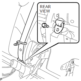
14. DISCONNECT REAR CENTER SEAT OUTER BELT ASSEMBLY
|
(a) Remove the bolt and disconnect the rear center seat outer belt assembly. |
|
15. REMOVE REAR SEATBACK BOARD RH
16. REMOVE REAR SEAT SHOULDER BELT COVER
|
(a) Remove the screw. |
|
.png)
|
(b) Disengage the 2 guides and disconnect the rear seatback upper lock bezel as shown in the illustration. |
|
.png)
|
(c) Disengage the claw and 2 guides, and remove the rear seat shoulder belt cover as shown in the illustration. |
|
.png)
17. REMOVE REAR SEAT HEADREST SUPPORT LH
18. REMOVE REAR SEAT HEADREST SUPPORT RH
19. REMOVE REAR SEAT CENTER HEADREST SUPPORT LH
20. REMOVE REAR SEAT CENTER HEADREST SUPPORT RH
21. REMOVE REAR SEATBACK COVER WITH PAD
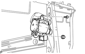
22. REMOVE REAR CENTER SEAT OUTER BELT ASSEMBLY
|
(a) Remove the bolt, nut, and the rear center seat outer belt assembly. |
|
 Components
COMPONENTS
ILLUSTRATION
ILLUSTRATION
ILLUSTRATION
...
 Installation
INSTALLATION
PROCEDURE
1. INSTALL REAR CENTER SEAT OUTER BELT ASSEMBLY
(a) Install the rear center seat outer belt assembly with the bolt and
nut.
Torque:
Bolt :
7.5 N·m ...
Other materials about Toyota Venza:
Power Window Master Switch
Components
COMPONENTS
ILLUSTRATION
Removal
REMOVAL
PROCEDURE
1. REMOVE POWER WINDOW REGULATOR MASTER SWITCH ASSEMBLY WITH FRONT DOOR ARMREST
BASE PANEL
2. REMOVE POWER WINDOW REGULATOR MASTER SWITCH ASSEMBLY
(a) Remove the 3 screw ...
Components
COMPONENTS
ILLUSTRATION
ILLUSTRATION
ILLUSTRATION
ILLUSTRATION
ILLUSTRATION
ILLUSTRATION
ILLUSTRATION
ILLUSTRATION
...
Front Left Sensor Malfunction (C1AE1)
DESCRIPTION
The No. 1 ultrasonic sensor (front left sensor) is installed on the front bumper.
The ECU detects obstacles based on signals received from the No. 1 ultrasonic sensor
(front left sensor). If the No. 1 ultrasonic sensor (front left sensor) has ...

0.1239