Toyota Venza: Front Passenger Side Solar Sensor Short Circuit (B14A3)
DESCRIPTION
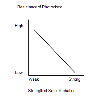
The solar sensor is installed on the upper side of the instrument panel. It detects sunlight to control air conditioning AUTO mode. The output voltage from the solar sensor varies in accordance with the amount of sunlight. When the amount of sunlight increases, the output voltage increases. As the sunlight decreases, the output voltage decreases. The A/C amplifier detects changes in the output voltage from the solar sensor.
|
DTC No. |
DTC Detection Condition |
Trouble Area |
|---|---|---|
|
B14A3 |
Short in passenger side solar sensor circuit |
|
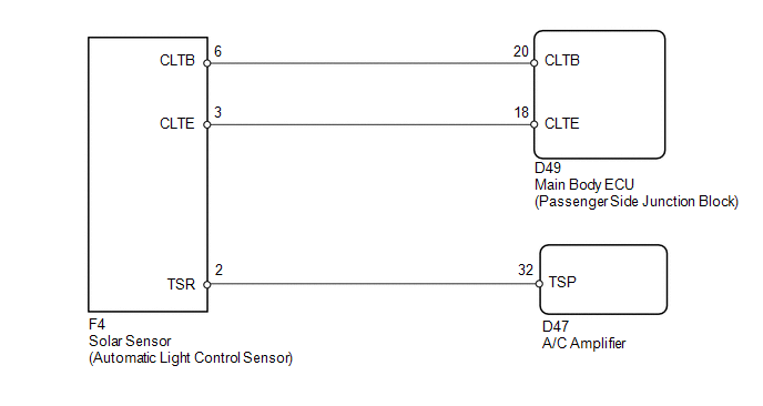
WIRING DIAGRAM
CAUTION / NOTICE / HINT
HINT:
If DTC B1244 is output together with other DTCs, troubleshoot DTC B1244 first
(See page .gif) ).
).
PROCEDURE
|
1. |
READ VALUE USING TECHSTREAM |
(a) Connect the Techstream to the DLC3.
(b) Turn the ignition switch to ON.
(c) Turn the Techstream on.
(d) Enter the following menus: Body / Air Conditioner / Data List.
(e) Check the value(s) by referring to the table below.
Air Conditioner|
Tester Display |
Measurement Item/Range |
Normal Condition |
Diagnostic Note |
|---|---|---|---|
|
Solar Sensor (P Side) |
Passenger side solar sensor / Min.: 0 Max.: 255 |
Passenger side solar sensor value increases as brightness increases |
- |
OK:
The display is as specified in the Normal Condition column.
|
Result |
Proceed to |
|---|---|
|
NG |
A |
|
OK (When troubleshooting according to Problem Symptoms Table) |
B |
|
OK (When troubleshooting according to the DTC) |
C |
| B | .gif) |
PROCEED TO NEXT SUSPECTED AREA SHOWN IN PROBLEM SYMPTOMS TABLE |
| C | |
REPLACE A/C AMPLIFIER |
|
.gif)
|
2. |
CHECK HARNESS AND CONNECTOR (POWER SOURCE CIRCUIT) |
|
(a) Disconnect the solar sensor connector. |
|
(b) Measure the voltage according to the value(s) in the table below.
Standard Voltage:
|
Tester Connection |
Condition |
Specified Condition |
|---|---|---|
|
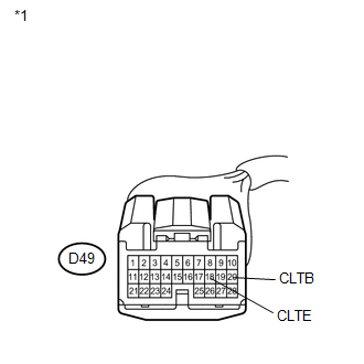
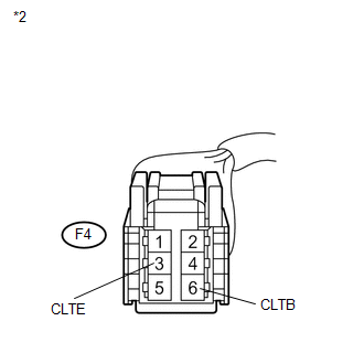
F4-6 (CLTB) - F4-3 (CLTE) |
Ignition switch off |
Below 1 V |
|
F4-6 (CLTB) - F4-3 (CLTE) |
Ignition switch ON |
11 to 14 V |
|
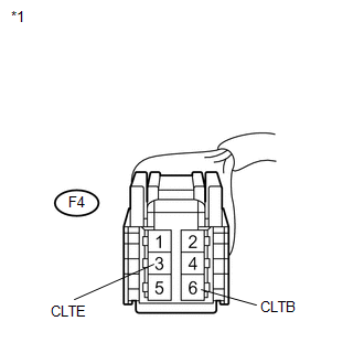
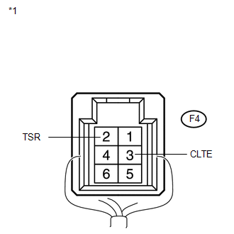
*1 |
Front view of wire harness connector (to Solar Sensor) |
| NG | |
GO TO STEP 5 |
|
|
3. |
CHECK HARNESS AND CONNECTOR (SOLAR SENSOR - A/C AMPLIFIER) |
|
(a) Disconnect the solar sensor connector. |
|
|
(b) Disconnect the A/C amplifier connector. |
|
(c) Measure the resistance according to the value(s) in the table below.
Standard Resistance:
|
Tester Connection |
Condition |
Specified Condition |
|---|---|---|
|
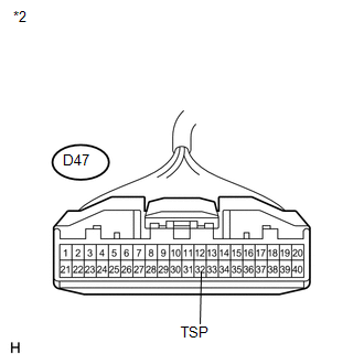
D47-32 (TSP) - F4-2 (TSR) |
Always |
Below 1 Ω |
|
D47-32 (TSP) - Body ground |
Always |
10 kΩ or higher |
|
*1 |
Front view of wire harness connector (to Solar Sensor) |
|
*2 |
Front view of wire harness connector (to A/C Amplifier) |
| NG | |
REPAIR OR REPLACE HARNESS OR CONNECTOR |
|
|
4. |
INSPECT SOLAR SENSOR |
|
(a) Remove the solar sensor. |
|
(b) Reconnect the solar sensor connector.
(c) Turn the ignition switch to ON.
(d) Measure the voltage according to the value(s) in the table below.
Standard Voltage:
|
Tester Connection |
Condition |
Specified Condition |
|---|---|---|
|
F4-2 (TSR) - F4-3 (CLTE) |
Sensor is subjected to electric light |
0.8 to 4.3 V |
|
F4-2 (TSR) - F4-3 (CLTE) |
Sensor is covered with a cloth |
Below 0.8 V |
NOTICE:
- The connection procedure for using a digital tester such as a TOYOTA electrical tester is shown above. When using an analog tester, connect the negative (-) lead to terminal 1 and the positive (+) lead to terminal 6 of the solar sensor.
- While using the battery during inspection, do not bring the positive and negative tester probes too close to each other as a short circuit may occur.
HINT:
- Use an incandescent light for inspection. Bring it within about 30 cm (11.8 in.) of the solar sensor.
- As the inspection light is moved away from the sensor, the voltage decreases.
|
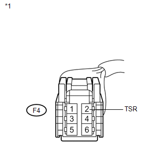
*1 |
Component with harness connected (Solar Sensor) |
| OK | |
REPLACE A/C AMPLIFIER |
| NG | |
REPLACE SOLAR SENSOR |
|
5. |
CHECK HARNESS AND CONNECTOR (MAIN BODY ECU - SOLAR SENSOR) |
|
(a) Disconnect the main body ECU connector. |
|
|
(b) Measure the resistance according to the value(s) in the table below. Standard Resistance:
|
|
| OK | |
REPLACE MAIN BODY ECU |
| NG | |
REPAIR OR REPLACE HARNESS OR CONNECTOR |
 Lost Communication with ECM (U0100-U0142,U0155)
DESCRIPTION
DTC No.
DTC Detecting Condition
Trouble Area
U0100
No communication with ECM
CAN communication system
...
 Driver Side Solar Sensor Short Circuit (B14A2)
DESCRIPTION
The solar sensor is installed on the upper side of the instrument panel. It detects
sunlight to control air conditioning AUTO mode. The output voltage from the solar
sensor varies i ...
Other materials about Toyota Venza:
On-vehicle Inspection
ON-VEHICLE INSPECTION
PROCEDURE
1. INSPECT ENGINE COOLANT
See page
2. INSPECT ENGINE OIL
See page
3. INSPECT BATTERY
See page
4. INSPECT AIR CLEANER FILTER ELEMENT SUB-ASSEMBLY
(a) Remove the air cleaner filter element sub-assembly.
(b) Visuall ...
Removal
REMOVAL
CAUTION / NOTICE / HINT
HINT:
Use the same procedure for the RH side and LH side.
The procedure listed below is for the LH side.
PROCEDURE
1. REMOVE REAR WHEEL
2. SEPARATE REAR DISC BRAKE CALIPER ASSEMBLY
3. REMOVE REAR DISC ...
How To Proceed With Troubleshooting
PROCEDURE
1.
CHECK TIRE AND WHEEL SYSTEM
DIAGNOSIS OF IRREGULAR TIRE WEAR
GO TO STEP 11
DIAGNOSIS OF TIRE VIBRATION
2.
...

0.1166