Toyota Venza: Dtc Check / Clear
DTC CHECK / CLEAR
1. CHECK DTC (When Using Techstream)
(a) Check the DTCs.
(1) Connect the Techstream to the DLC3.
(2) Turn the ignition switch to ON.
(3) Turn the Techstream on.
(4) Read the DTCs following the prompts on the Techstream screen. Enter the following menus: Chassis / 4WD / Trouble Codes.
(5) Check the details of the DTCs (See page .gif)
).
2. CLEAR DTC (When Using Techstream)
(a) Clear the DTCs.
(1) Connect the Techstream to the DLC3.
(2) Turn the ignition switch to ON.
(3) Turn the Techstream on.
(4) Operate the Techstream to clear the DTCs. Enter the following menus: Chassis / 4WD / Trouble Codes.
(5) According to the display on the Techstream, select the trouble code data display with the clear button.
3. CHECK DTC (When not Using Techstream)
(a) Check the DTCs.
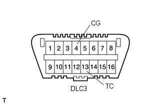
(1) Using SST, connect terminals TC (13) and CG (4) of the DLC3.
SST: 09843-18040
(2) Turn the ignition switch to ON.
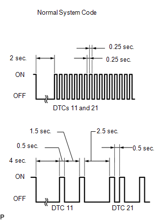
(3) Read DTCs from the AWD warning light on the combination meter.
HINT:
- If the AWD warning light does not blink, perform relevant troubleshooting procedures. The relevant troubleshooting procedures are in the sections listed in the table below.
- If more than 1 DTC is detected at the same time, the DTCs will be displayed in numerical order.
- As an example, the blinking patterns of the normal system code and DTCs 11 and 21 are shown below.
- DTCs are explained in Diagnostic Trouble Code Chart (See page
).
|
Section Title |
See Procedure |
|---|---|
|
AWD warning light does not Come ON |
|
|
TC and CG Terminal Circuit |
|
4. CLEAR DTC (When not Using Techstream)
(a) Using SST, connect terminals 13 (TC) and 4 (CG) of the DLC3.
SST: 09843-18040
(b) Turn the ignition switch to ON.
(c) Clear the DTCs stored in the AWD control ECU by depressing the brake pedal 8 times or more within 5 seconds.
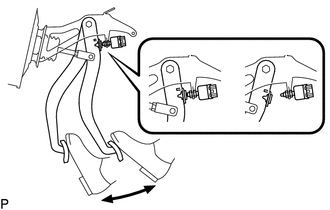
(d) Check that the warning light blinks in the normal system code pattern.
(e) Remove SST from the terminals of the DLC3.
(f) Turn the ignition switch off.
HINT:
DTCs cannot be cleared by disconnecting the cable from the negative (-) battery terminal or removing the ECU-IG1 fuse.
 Diagnosis System
DIAGNOSIS SYSTEM
1. DESCRIPTION
Active torque control 4WD system data can be read in the Data Link Connector
3 (DLC3) of the vehicle. When the system seems to be malfunctioning, use the Techstream ...
 Data List / Active Test
DATA LIST / ACTIVE TEST
HINT:
Using the Techstream to read the Data List allows the values or states of switches,
sensors, actuators and other items to be read without removing any parts. This non ...
Other materials about Toyota Venza:
Fog Light Assembly
Components
COMPONENTS
ILLUSTRATION
Disassembly
DISASSEMBLY
PROCEDURE
1. REMOVE FOG LIGHT BULB
(a) Turn the fog light bulb in the direction indicated by the arrow shown
in the illustration and remove it.
NOTICE:
Do not touch th ...
Short in Curtain Shield Squib RH Circuit (B1830/57-B1833/57)
DESCRIPTION
The curtain shield squib RH circuit consists of the center airbag sensor assembly
and curtain shield airbag assembly RH.
The center airbag sensor assembly uses this circuit to deploy the airbag when
deployment conditions are met.
These DTCs ...
Terminals Of Ecu
TERMINALS OF ECU
1. CHECK TRANSPONDER KEY AMPLIFIER
(a) Disconnect the D21 transponder key amplifier connector.
(b) Measure the resistance according to the value(s) in the table below.
HINT:
Measure the values on the wire harness side with connector dis ...

0.1478