Toyota Venza: Installation
INSTALLATION
PROCEDURE
1. INSTALL INSTRUMENT PANEL STAY
|
(a) Engage the 3 claws to install the 3 instrument panel stays. |
|
.png)
2. INSTALL INSTRUMENT PANEL CLIP
|
(a) Engage the 2 claws to install the 2 instrument panel clips. |
|
.png)
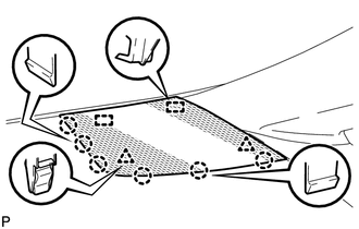
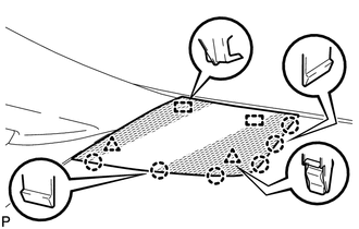
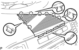
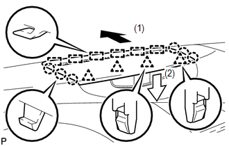
3. INSTALL INSTRUMENT PANEL SAFETY PAD ASSEMBLY
(a) Engage the 4 claws and guide, and temporarily install the instrument panel safety pad assembly as shown in the illustration.
(b) Install the 2 passenger airbag bolts <A> or <B>.
Torque:
20 N·m {204 kgf·cm, 15 ft·lbf}
(c) Install the instrument panel safety pad assembly with the 2 bolts <C> and nut <G> or <H>.
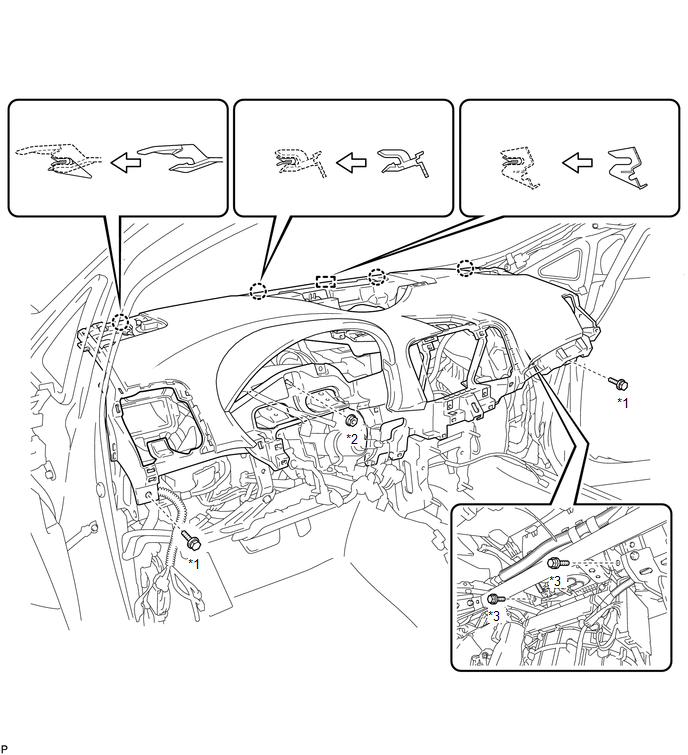 Text in Illustration
|
*1 |
Bolt <C> |
|
*2 |
Nut <G> or <H> |
|
*3 |
Bolt <A> or <B> |
(d) Install the bolt <D>.
Torque:
8.0 N·m {82 kgf·cm, 71 in·lbf}
(e) Connect the connectors.
.png)
4. CONNECT INSTRUMENT PANEL WIRE ASSEMBLY
.gif)
5. INSTALL SHIFT LEVER ASSEMBLY
for U660F: (See page )
for U660E: (See page )
for U760E: (See page )
for U760F: (See page )
6. INSTALL NO. 4 INSTRUMENT PANEL REGISTER ASSEMBLY
|
(a) Engage the 4 claws, 2 clips and guide to install the No. 4 instrument panel register assembly. |
|
.png)
7. INSTALL FRONT PILLAR GARNISH CORNER PIECE RH (for 6 Speakers)
|
(a) Engage the 3 claws to install the front pillar garnish corner piece RH. |
|
.png)
8. INSTALL FRONT PILLAR GARNISH CORNER PIECE RH (for 13 Speakers)
|
(a) Connect the connector. |
|
.png)
(b) Engage the clamp.
|
(c) Engage the 3 claws to install the front pillar garnish corner piece RH. |
|
.png)
9. INSTALL FRONT PILLAR GARNISH RH
HINT:
Use the same procedure as for the LH side (See page
).
10. CONNECT FRONT DOOR OPENING TRIM WEATHERSTRIP RH
11. INSTALL FRONT NO. 2 SPEAKER ASSEMBLY (for RH Side)
HINT:
Use the same procedure as for the LH side (See page
).
12. INSTALL NO. 3 INSTRUMENT PANEL SPEAKER PANEL SUB-ASSEMBLY
|
(a) Engage the 2 guides, 6 claws and 2 clips to install the No. 3 instrument panel speaker panel sub-assembly. |
|
13. INSTALL NO. 1 INSTRUMENT PANEL REGISTER ASSEMBLY
|
(a) Engage the 4 claws, 2 clips and guide to install the No. 1 instrument panel register assembly. |
|
.png)
14. INSTALL FRONT PILLAR GARNISH CORNER PIECE LH (for 6 Speakers)
|
(a) Engage the 3 claws to install the front pillar garnish corner piece LH. |
|
.png)
15. INSTALL FRONT PILLAR GARNISH CORNER PIECE LH (for 13 Speakers)
|
(a) Connect the connector. |
|
.png)
(b) Engage the clamp.
|
(c) Engage the 3 claws to install the front pillar garnish corner piece LH. |
|
.png)
16. INSTALL FRONT PILLAR GARNISH LH
17. CONNECT FRONT DOOR OPENING TRIM WEATHERSTRIP LH
18. INSTALL FRONT NO. 2 SPEAKER ASSEMBLY (for LH Side)
19. INSTALL NO. 1 INSTRUMENT PANEL SPEAKER PANEL SUB-ASSEMBLY
|
(a) Engage the 2 guides, 6 claws and 2 clips to install the No. 1 instrument panel speaker panel sub-assembly. |
|
20. INSTALL LOWER INSTRUMENT PANEL FINISH PANEL (w/o Smart Key System)
|
(a) Engage the 4 claws to install the lower instrument panel finish panel. |
|
.png)
21. INSTALL LOWER INSTRUMENT PANEL FINISH PANEL (w/ Smart Key System)
|
(a) Connect the connector. |
|
.png)
(b) Engage the 4 claws to install the lower instrument panel finish panel.
22. INSTALL RADIO AND DISPLAY RECEIVER ASSEMBLY WITH BRACKET (for Radio and Display Type)
23. INSTALL NAVIGATION RECEIVER ASSEMBLY WITH BRACKET (for Navigation Receiver Type)
24. INSTALL FRONT NO. 4 SPEAKER ASSEMBLY (for 13 Speakers)
25. INSTALL NO. 2 INSTRUMENT PANEL SPEAKER PANEL SUB-ASSEMBLY
|
(a) Engage the 4 guides and 9 claws to install the No. 2 instrument panel speaker panel sub-assembly. |
|
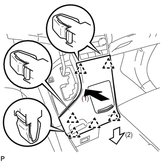
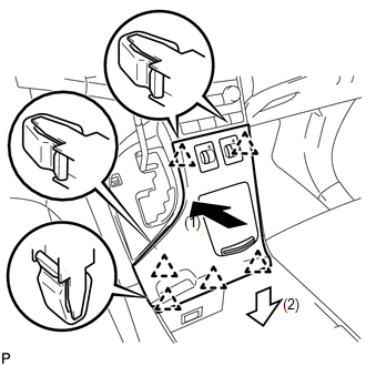
26. INSTALL CONSOLE BOX SUB-ASSEMBLY
|
(a) Engage the 2 claws and 4 clips. |
|
.png)
|
(b) Engage the 2 clamps. |
|
.png)
(c) Connect the connector.
(d) Install the clip.
(e) Install the console box sub-assembly with the 2 screws <E> or <F>.
27. INSTALL POSITION INDICATOR HOUSING ASSEMBLY
|
(a) Engage the 3 clips to position indicator housing assembly. |
|
.png)
(b) Connect the connector.
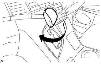
(c) Move the shift lever to P.
28. INSTALL SHIFT LEVER KNOB SUB-ASSEMBLY
|
(a) Turn the shift lever knob clockwise to install the shift lever knob sub-assembly. |
|
29. INSTALL LOWER INSTRUMENT PANEL SUB-ASSEMBLY
|
(a) Connect the connectors. |
|
.png)
(b) Engage the 5 guides, 2 clips and claw.
|
(c) Install the lower instrument panel sub-assembly with the bolt <C> and 4 screws <E> or <F>. |
|
.png)
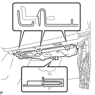
30. INSTALL NO. 2 INSTRUMENT PANEL UNDER COVER SUB-ASSEMBLY
|
(a) Engage the guide and 3 claws to install the No. 2 instrument panel under cover sub-assembly. |
|
31. INSTALL COWL SIDE TRIM SUB-ASSEMBLY RH
HINT:
Use the same procedure as for the LH side (See page
).
32. INSTALL FRONT DOOR SCUFF PLATE RH
HINT:
Use the same procedure as for the LH side (See page
).
33. INSTALL LOWER NO. 1 INSTRUMENT PANEL FINISH PANEL
|
(a) Connect the hood lock control cable. |
|
.png)
|
(b) Connect the aspirator duct and connector. |
|
.png)
|
(c) Connect the connectors. |
|
.png)
(d) Engage the claw and 9 clips.
(e) Install the lower No. 1 instrument panel finish panel with the bolt <C> and screw <E> or <F>.
34. INSTALL COWL SIDE TRIM SUB-ASSEMBLY LH
35. INSTALL FRONT DOOR SCUFF PLATE LH
36. INSTALL AIR CONDITIONING CONTROL ASSEMBLY
37. INSTALL CONSOLE BOX ASSEMBLY
38. INSTALL NO. 2 CONSOLE BOX CARPET
39. INSTALL UPPER CONSOLE PANEL SUB-ASSEMBLY (w/o Seat Heater System)
|
(a) Engage the 6 clips to install the upper console panel sub-assembly as shown in the illustration. |
|
40. INSTALL UPPER CONSOLE PANEL SUB-ASSEMBLY (w/ Seat Heater System)
|
(a) Connect the connectors. |
|
(b) Engage the 6 clips to install the upper console panel sub-assembly as shown in the illustration.
41. INSTALL ACCESSORY METER ASSEMBLY (w/o Rear View Monitor System)
42. INSTALL ACCESSORY METER ASSEMBLY (w/ Rear View Monitor System)
43. INSTALL DEFROSTER NOZZLE GARNISH
|
(a) Connect the connector. |
|
.png)
|
(b) Engage the 6 guides, 6 claws and 4 clips to install the defroster nozzle garnish as shown in the illustration. |
|
44. INSTALL COMBINATION METER ASSEMBLY
45. INSTALL INSTRUMENT CLUSTER FINISH PANEL
46. INSTALL TURN SIGNAL SWITCH ASSEMBLY WITH SPIRAL CABLE SUB-ASSEMBLY
47. INSTALL UPPER STEERING COLUMN COVER
48. INSTALL LOWER STEERING COLUMN COVER
49. ALIGN FRONT WHEELS FACING STRAIGHT AHEAD
50. ADJUST SPIRAL CABLE
51. INSTALL STEERING WHEEL ASSEMBLY
52. INSTALL STEERING PAD
(See page )
53. INSPECT STEERING WHEEL CENTER POINT
54. CONNECT CABLE TO NEGATIVE BATTERY TERMINAL
NOTICE:
When disconnecting the cable, some systems need to be initialized after the cable
is reconnected (See page ).
55. INSPECT STEERING PAD
56. INSPECT SHIFT LEVER POSITION
for U660F: (See page )
for U660E: (See page )
for U760E: (See page )
for U760F: (See page )
57. ADJUST SHIFT LEVER POSITION
for U660F: (See page )
for U660E: (See page )
for U760E: (See page )
for U760F: (See page )
58. INSPECT SRS WARNING LIGHT
(a) Inspect the SRS warning light (See page
).
 Reassembly
REASSEMBLY
PROCEDURE
1. INSTALL NO. 1 INSTRUMENT PANEL PIN
(a) Install the 2 No. 1 instrument panel pins with the 2 screws <E> or
<F>.
...
 Roof Headlining
...
Other materials about Toyota Venza:
Communication Malfunction No. 1 (B2797)
DESCRIPTION
This DTC is stored when an error occurs in communication between the transponder
key amplifier and the transponder key ECU assembly.
HINT:
Some noise is found in the communication line.
DTC No.
DTC Detection Condition
...
Fail-safe Chart
FAIL-SAFE CHART
If a problem occurs in the power steering system, the power steering assist will
be stopped or the amount of power assist will be decreased to protect the system.
Power Steering System
Malfunction
Fail-safe Operation
...
Operation Check
OPERATION CHECK
1. CHECK FUNCTION
(a) Check that the key reminder warning buzzer sounds.
(1) With the driver side door closed, insert the key into the ignition key cylinder
and then make sure that the key is in LOCK or ACC.
(2) Check that the buzzer soun ...

0.1219