Toyota Venza: Installation
INSTALLATION
PROCEDURE
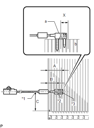
1. INSTALL NO. 1 COOLER THERMISTOR
|
(a) Install the No. 1 cooler thermistor as shown in the illustration.
NOTICE:
|
|
|||||||||||||||||||
2. INSTALL COOLER EVAPORATOR SUB-ASSEMBLY
.gif)
3. INSTALL BLOWER ASSEMBLY WITH COOLER EVAPORATOR SUB-ASSEMBLY
4. INSTALL COOLER EXPANSION VALVE
5. INSTALL AIR CONDITIONING HARNESS ASSEMBLY
6. INSTALL NO. 2 AIR DUCT SUB-ASSEMBLY
7. INSTALL NO. 3 AIR DUCT SUB-ASSEMBLY
8. INSTALL NO. 2 FINISH PANEL MOUNTING BRACKET
9. INSTALL NO. 1 FINISH PANEL MOUNTING BRACKET
10. INSTALL AIR CONDITIONING UNIT ASSEMBLY
(See page )
 Inspection
INSPECTION
PROCEDURE
1. INSPECT EVAPORATOR TEMPERATURE SENSOR
(a) Measure the resistance according to the value(s) in the table below.
Standard Resistance:
Tester Connection
...
 Refrigerant
...
Other materials about Toyota Venza:
Problem Symptoms Table
PROBLEM SYMPTOMS TABLE
Use the table below to help determine the cause of problem symptoms. If multiple
suspected areas are listed, the potential causes of the symptoms are listed in order
of probability in the "Suspected Area" column of the tab ...
Problem Symptoms Table
PROBLEM SYMPTOMS TABLE
HINT:
Use the table below to help determine the cause of problem symptoms.
If multiple suspected areas are listed, the potential causes of the symptoms
are listed in order of probability in the "Suspected Area" ...
Vehicle Speed or Engine Speed Signal Malfunction (C2173/73)
DESCRIPTION
The tire pressure warning ECU receives a vehicle speed signal from the combination
meter and an engine speed signal from the ECM. The tire pressure warning ECU uses
these signals to detect DTCs C2121/21 to C2124/24 (No Signal from Transmitter) ...

0.1359