Toyota Venza: Reassembly
REASSEMBLY
PROCEDURE
1. INSTALL MAGNETIC CLUTCH ASSEMBLY
|
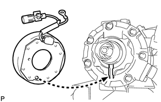
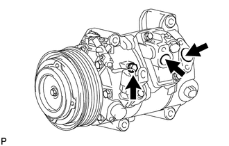
(a) Install the magnetic clutch stator while aligning the protrusion on the stator with the notch on the air compressor assembly as shown in the illustration. |
|
|
(b) Engage the clamp. |
|
.png)
(c) Install the bracket with the screw.
(d) Connect the connector.
|
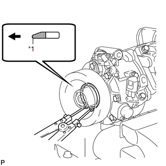
(e) Using a snap ring expander, install a new snap ring with the chamfered side facing up. Text in Illustration
NOTICE: Take care not to damage the seal cover of the bearing when installing the snap ring. |
|
|
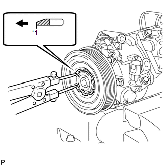
(f) Using a snap ring expander, install the magnetic clutch rotor and a new snap ring with the chamfered side facing up. Text in Illustration
NOTICE:
|
|
(g) Install the magnetic clutch washers and magnetic clutch hub.
NOTICE:
Do not change the combination of the magnetic clutch washers used before disassembly.
|
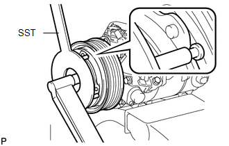
(h) Using SST, hold the magnetic clutch hub and install the bolt. SST: 09985-00270 Torque: 18 N·m {184 kgf·cm, 13 ft·lbf} NOTICE: Make sure that there is no foreign matter or oil on the compressor shaft, bolt and clutch hub. |
|
2. INSPECT MAGNETIC CLUTCH CLEARANCE
|
(a) Set the dial indicator to the magnetic clutch hub. |
|
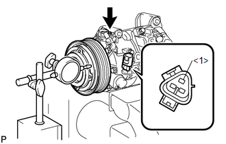
(b) Connect a positive (+) lead from the battery to terminal 1 of the magnetic clutch connector, and a negative (-) lead to the ground wire. Turn the magnetic clutch on and off and measure the clearance.
Standard clearance:
0.26 to 0.60 mm (0.0103 to 0.0236 in.)
If the measured value is not within the standard range, remove the magnetic clutch hub and adjust it with magnetic clutch washers.
NOTICE:
Adjustment should be performed with 3 or less magnetic clutch washers.
(c) Remove the compressor and magnetic clutch from the vise.
3. ADJUST COMPRESSOR OIL LEVEL
|
(a) When replacing the compressor and magnetic clutch with a new one, gradually discharge the refrigerant from the service valve, and drain the following amount of oil from the new compressor and magnetic clutch before installation. Standard: (Oil capacity inside the new compressor and magnetic clutch: 130 + 15 cc (4.4 + 0.51 fl.oz.) ) - (Remaining oil amount in the removed compressor and magnetic clutch) = (Oil amount to be removed from the new compressor when replacing) NOTICE:
|
|
 Installation
INSTALLATION
PROCEDURE
1. TEMPORARILY TIGHTEN COMPRESSOR AND MAGNETIC CLUTCH
(a) Temporarily install the compressor and magnetic clutch and bracket
with the 4 bolts.
...
 Condenser
...
Other materials about Toyota Venza:
Installation
INSTALLATION
CAUTION / NOTICE / HINT
HINT:
Use the same procedure for the RH side and LH side.
The procedure listed below is for the LH side.
PROCEDURE
1. INSTALL FRONT AIRBAG SENSOR
(a) Check that the ignition switch is off.
(b) Check ...
Initialization
INITIALIZATION
1. INITIALIZE SLIDING ROOF ECU (SLIDING ROOF DRIVE GEAR SUB-ASSEMBLY)
NOTICE:
When the sliding roof glass, sliding roof housing or sliding roof ECU
(sliding roof drive gear sub-assembly) is replaced or removed and installed,
t ...
Reassembly
REASSEMBLY
PROCEDURE
1. INSTALL GENERATOR ROTOR ASSEMBLY
(a) Place the drive end frame on the clutch pulley.
(b) Install the generator rotor assembly to the drive end frame.
2. INSTALL GENERATOR CL ...

0.1518