Toyota Venza: Installation
INSTALLATION
PROCEDURE
1. CLEAN FRONT SIDE FIX WINDOW ASSEMBLY
|
(a) Clean the outer edges of the front side fix window assembly with a non-residue solvent. NOTICE:
|
|
2. INSTALL FRONT SIDE FIX WINDOW ASSEMBLY
(a) Using a brush or a sponge, apply Primer M to the exposed part of the vehicle body.
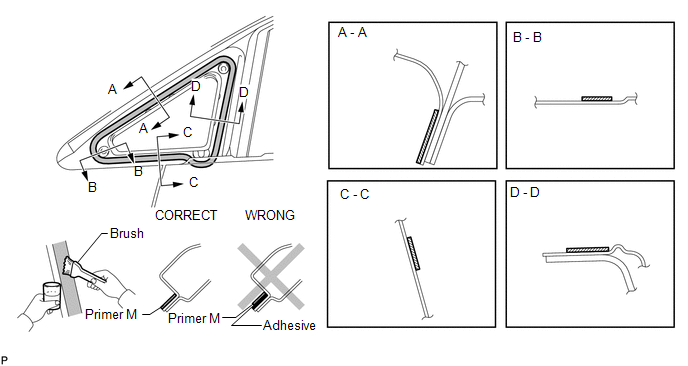
NOTICE:
- Do not coat the adhesive with Primer M.
- Do not apply too much primer.
- Allow the primer to dry for 3 minutes or more.
- Throw away any leftover primer.
(b) Using a brush or a sponge, apply Primer G to the contact surface of the front side fix window assembly.
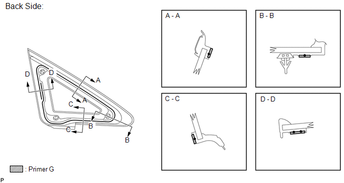
HINT:
If an area other than that specified, wipe off the primer with a non-residue solvent before it dries.
NOTICE:
- To prevent the glass from breaking at low temperatures, ensure that no primer adheres to the contact surface between the moulding and glass during application.
- Allow the primer to dry for 3 minutes or more.
- Throw away any leftover primer.
- Do not apply too much primer.
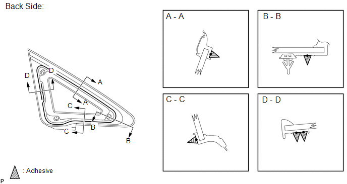
(c) Apply adhesive to the front side fix window assembly.
Adhesive:
Toyota Genuine Windshield Glass Adhesive or equivalent
|
(1) Cut off the tip of the cartridge nozzle as shown in the illustration. Standard Dimension:
|
|
(2) Load the sealer gun with cartridge.
(3) Apply adhesive to the front side fix window assembly as shown in the illustration.
(d) Install the front side fix window assembly to the vehicle body.
|
(1) Position the front side fix window assembly so that the matchmarks are aligned, and press it in gently along the rim (when a window with missing clips is used). Text in Illustration
|
|
(2) Lightly press the front side fix window assembly to ensure that the front side fix window assembly is securely fit to the vehicle body (when a window with missing clips is used).
HINT:
Press the glass with a force of 98 N (10 kgf, 22 lbf) or more.
|
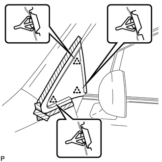
(3) Engage the 3 clips to install the front side fix window assembly (when a window without missing clips is used). |
|
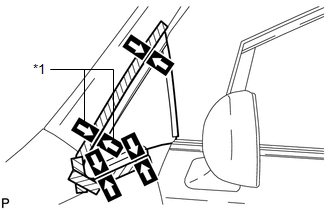
(4) Hold the front side fix window assembly in place securely with protective tape or equivalent until the adhesive hardens.
NOTICE:
- Allow the primer to dry for 3 minutes or more.
- Check that the clips are attached to the body correctly.
- Check the clearance between the body and glass.
(5) Lightly press the outer surface of the glass to ensure that the glass is securely fit to the vehicle body.
|
(6) Using a scraper, remove any excess or protruding adhesive. HINT: Apply adhesive onto the glass rim. NOTICE: Do not drive the vehicle within the time described in the table below. Minimum Time:
|
|
3. INSPECT FOR LEAK AND REPAIR
(a) After the adhesive has hardened, apply water from the outside of the vehicle. Check that no water leaks into the cabin.
(b) If water leaks into the cabin, allow the water to dry and add adhesive.
(c) Remove the protective tape.
4. INSTALL FRONT PILLAR GARNISH CORNER PIECE (for 6 Speakers)
.gif)
5. INSTALL FRONT PILLAR GARNISH CORNER PIECE (for 13 Speakers)
.gif)
6. INSTALL FRONT PILLAR GARNISH
.gif)
7. INSTALL FRONT DOOR OPENING TRIM WEATHERSTRIP
.gif)
 Components
COMPONENTS
ILLUSTRATION
...
 Removal
REMOVAL
CAUTION / NOTICE / HINT
HINT:
The front side fix window assembly can be reused. When installing the
window, if any of the clips on the front side fix window assembly are broken, ...
Other materials about Toyota Venza:
Removal
REMOVAL
PROCEDURE
1. REMOVE ENGINE ASSEMBLY WITH TRANSAXLE
See page for 2GR-FE
See page for 1AR-FE
2. REMOVE FRONT NO. 1 STABILIZER BRACKET LH
3. REMOVE FRONT NO. 1 STABILIZER BRACKET RH
HINT:
Perform the same procedure as for the LH side.
4. REM ...
Terminals Of Ecu
TERMINALS OF ECU
1. CHECK MAIN BODY ECU (DRIVER SIDE JUNCTION BLOCK ASSEMBLY)
(a) Disconnect the 2A, 2C and 2F main body ECU (driver side junction block assembly)
connectors.
(b) Measure the voltage and resistance according to the value(s) in the table ...
Rear Left Sensor Malfunction (C1AE6)
DESCRIPTION
The No. 1 ultrasonic sensor (rear left sensor) is installed on the rear bumper.
The ECU detects obstacles based on signals received from the No. 1 ultrasonic sensor
(rear left sensor). If the No. 1 ultrasonic sensor (rear left sensor) has an o ...
0.1381

.png)
.png)
.png)