Toyota Venza: Components
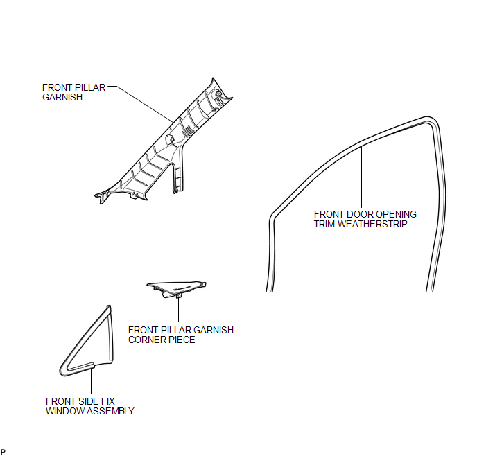
COMPONENTS
ILLUSTRATION

 Installation
INSTALLATION
PROCEDURE
1. CLEAN FRONT SIDE FIX WINDOW ASSEMBLY
(a) Clean the outer edges of the front side fix window assembly with
a non-residue solvent.
NOTICE:
...
Other materials about Toyota Venza:
Reassembly
REASSEMBLY
PROCEDURE
1. INSTALL FRONT OIL PUMP OIL SEAL
(a) Using SST and a hammer, install a new oil seal to the oil pump body.
SST: 09350-32014
09351-32140
Oil seal driven in depth:
-0.25 to 0.25 mm (-0.00984 to 0.00984 in.)
...
Engine Immobiliser System Malfunction (B2799)
DESCRIPTION
This DTC is stored when one of the following occurs: 1) the ECM detects an error
in its own communication with the certification ECU (smart key ECU assembly); 2)
the ECM detects an error in the communication lines; or 3) the ECU communication ...
Removal
REMOVAL
CAUTION / NOTICE / HINT
NOTICE:
Release the vacuum from the booster by depressing the brake pedal several times.
Then remove the brake master cylinder from the brake booster.
PROCEDURE
1. REMOVE FRONT WIPER ARM HEAD CAP
2. REMOVE FRONT WIPER AR ...

0.171