Toyota Venza: Components
COMPONENTS
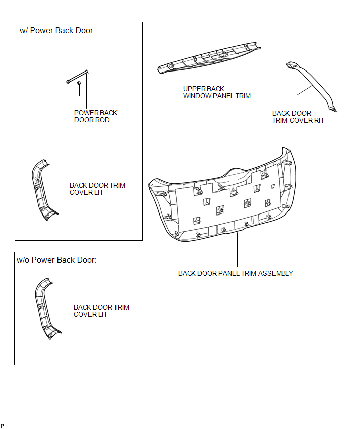
ILLUSTRATION
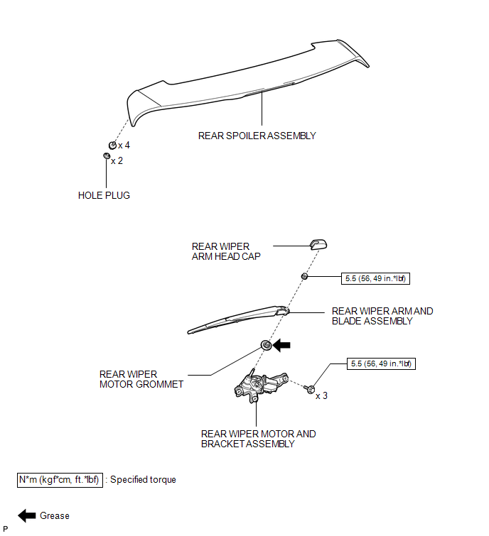
ILLUSTRATION
ILLUSTRATION
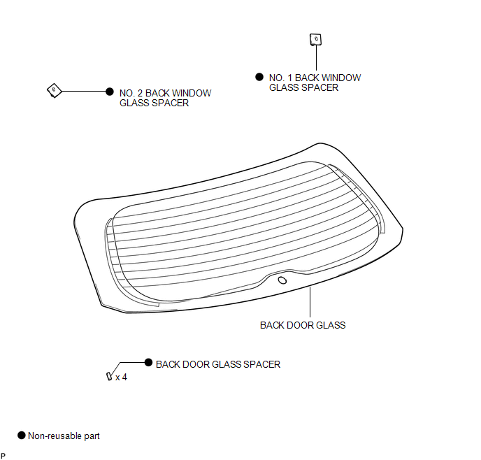
 Back Door Glass
...
 Installation
INSTALLATION
PROCEDURE
1. INSTALL NO. 2 BACK WINDOW GLASS SPACER
(a) Apply Primer G to the installation part of the No. 2 back window glass spacer.
HINT:
If primer is applied to an area that is n ...
Other materials about Toyota Venza:
Lost Communication with Power Source Control (B278C)
DESCRIPTION
This DTC is stored when LIN communication between the certification ECU (smart
key ECU assembly) and power management control ECU stops for more than 10 seconds.
DTC Code
DTC Detection Condition
Trouble Area
...
Diagnosis System
DIAGNOSIS SYSTEM
1. DESCRIPTION
(a) Diagnostic System
When troubleshooting a vehicle with a diagnostic system, the only difference
from the usual troubleshooting procedure is connecting the Techstream to the vehicle
and reading various data output from ...
Short in Driver Side Squib 2nd Step Circuit (B1810/53-B1813/53)
DESCRIPTION
The driver side squib 2nd step circuit consists of the center airbag sensor assembly,
spiral cable and steering pad.
The center airbag sensor assembly uses this circuit to deploy the airbag when
deployment conditions are met.
These DTCs are ...

0.1222