Toyota Venza: Automatic High Beam Mirror (B124A)
DESCRIPTION
The DTC is stored when the main body ECU (driver side junction block assembly) detects malfunctions in the inner rear view mirror assembly.
|
DTC No. |
DTC Detection Condition |
Trouble Area |
|---|---|---|
|
B124A |
Malfunction in inner rear view mirror assembly |
Inner rear view mirror assembly |
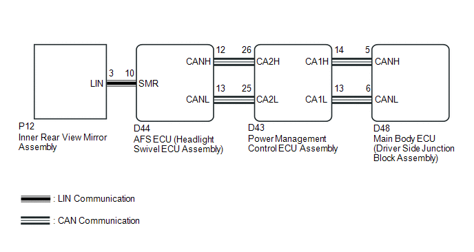
WIRING DIAGRAM
CAUTION / NOTICE / HINT
NOTICE:
First perform the communication function inspections in How to Proceed with Troubleshooting to confirm that there are no CAN communication malfunctions before troubleshooting this symptom.
PROCEDURE
|
1. |
CHECK FOR DTC |
(a) Clear the DTCs (See page .gif) ).
).
(b) Check for DTCs (See page ).
OK:
DTC B124A is not output.
| OK | .gif) |
USE SIMULATION METHOD TO CHECK |
| NG | |
REPLACE INNER REAR VIEW MIRROR ASSEMBLY |
 Lost Communication with ECM (U0101,U0073,U0126,U0129,U0142,U0182,U1000)
DESCRIPTION
The DTCs are stored when the CAN communication system is malfunctioning.
DTC No.
DTC Detection Condition
Trouble Area
U0101
L ...
 Automatic High Beam System (B124B)
DESCRIPTION
The DTC is stored when the main body ECU (driver side junction block assembly)
detects malfunctions in the automatic high beam system.
DTC No.
DTC Detection Condi ...
Other materials about Toyota Venza:
Reassembly
REASSEMBLY
PROCEDURE
1. INSTALL FRONT SEAT WIRE RH (for Front Passenger Side)
(a) Engage each clamp and install the front seat wire RH.
2. INSTALL OCCUPANT CLASSIFICATION ECU (for Front Passenger Side)
3. INSTALL SEAT POSITION SENSOR
4. INSTALL SEA ...
Push Switch / Key Unlock Warning Switch Malfunction (B2780)
DESCRIPTION
This DTC is stored if the transponder key ECU assembly does not detect that the
unlock warning switch assembly is ON even when the ignition switch is ON. Under
normal conditions, the unlock warning switch assembly is ON when the ignition switc ...
Installation
INSTALLATION
PROCEDURE
1. INSTALL INSTRUMENT PANEL WIRE ASSEMBLY
(a) Connect the vent hole connector of the instrument panel wire to the
front passenger airbag assembly.
Text in Illustration
*1
Vent Hol ...

0.1321