Toyota Venza: Installation
INSTALLATION
PROCEDURE
1. INSTALL FRONT DOOR BELT MOULDING
|
(a) Engage the 5 claws to install the front door belt moulding. |
|
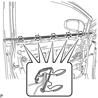
(b) Install the clip.
2. INSTALL FRONT DOOR GLASS RUN
.gif)
3. INSTALL FRONT DOOR GLASS SUB-ASSEMBLY
4. INSTALL FRONT DOOR SERVICE HOLE COVER
5. INSTALL FRONT NO. 1 SPEAKER ASSEMBLY
6. INSTALL DOOR SIDE AIRBAG SENSOR
7. INSTALL FRONT DOOR INSIDE HANDLE SUB-ASSEMBLY
8. INSTALL FRONT DOOR TRIM BOARD SUB-ASSEMBLY
9. INSTALL COURTESY LIGHT ASSEMBLY
10. INSTALL POWER WINDOW REGULATOR MASTER SWITCH ASSEMBLY WITH FRONT DOOR ARMREST BASE PANEL (for Driver Side)
11. INSTALL POWER WINDOW REGULATOR SWITCH ASSEMBLY WITH FRONT DOOR ARMREST BASE PANEL (for Front Passenger Side)
12. INSTALL FRONT DOOR INSIDE HANDLE BEZEL PLUG
13. CONNECT CABLE TO NEGATIVE BATTERY TERMINAL
NOTICE:
When disconnecting the cable, some systems need to be initialized after the cable
is reconnected (See page ).
14. INSPECT SRS WARNING LIGHT
(See page )
15. INITIALIZE POWER WINDOW CONTROL SYSTEM
(See page )
 Components
COMPONENTS
ILLUSTRATION
ILLUSTRATION
...
 Removal
REMOVAL
PROCEDURE
1. DISCONNECT CABLE FROM NEGATIVE BATTERY TERMINAL
CAUTION:
Wait at least 90 seconds after disconnecting the cable from the negative (-)
battery terminal to disable the SRS sys ...
Other materials about Toyota Venza:
Definition Of Terms
DEFINITION OF TERMS
Term
Definition
Monitor description
Description of what the TCM monitors and how it detects malfunctions
(monitoring purpose and its details).
Related DTCs
D ...
Problem Symptoms Table
PROBLEM SYMPTOMS TABLE
HINT:
Use the table below to help determine the cause of problem symptoms.
If multiple suspected areas are listed, the potential causes of the symptoms
are listed in order of probability in the "Suspected Area" ...
Using the AUX port/USB port
This port can be used to connect a portable audio device and listen to it
through the vehicle’s speakers.
Open the cover.
Connect the portable audio device.
- Operating portable audio devices connected to the audio system
The volume can be adj ...

0.1467